TP-6461 1/0890 Section 6 Component Replacement, Model KSS
8. Remove the suspect microswitch.
9. Install the new microswitch.
10. Install the holding screws.
11. Tighten the holding screws to 0.3 Nm (3 in. lb.).
12. Connect the fast-on connections to the
microswitch terminals as noted in step 5.
13. Close the transfer switch enclosure.
14. Connect power to the ATS.
15. Enable the generator set startup.
a. Check that the generator set master switch is in
the OFF position.
b. Reconnect the generator set engine starting
battery, negative (--) lead last.
c. Reconnect power to the battery charger, if
equipped.
16. Test the transfer switch operation by performing
the Automatic Operation Test described in
Section 4.5.4.
Note: Do not leave the transfer switch in the Test
mode.
6.3 Power Panel Replacement
Required tools and equipment:
Basic electricians hand tools
Multimeter digital or analog
Wiring harness
Tie wraps
Required protective equipment:
Rubber insulating gloves class 0
Safety glasses
Electrical hazard safety shoes
Power Panel Replacement Procedure
1. Disable all connected generator sets.
2. Disconnect primary and emergency power to the
transfer switch.
3. Open the enclosure.
4. Check for zero volts on the normal and emergency
power lugs.
5. Remove the tie wraps securing the harness.
6. Disconnect the power panel harness from the
controller harness.
Note: The replacement power panel is shipped
with a factory-wired power panel harness.
7. Disconnect the engine start leads from the ATS
engine start terminals.
8. Disconnect the emergency power supply cables
from the switch.
Note: Mark each cable as to its position as it is
removed from the switch. Example: E1, E2
and E3 for the emergency side of the switch.
9. Disconnect the normal power supply cables from
the switch, marking the cables as they are
removed.
10. Disconnect the load cables from the switch,
marking the cables as they are removed.
11. Remove the four nuts securing the power panel.
12. Remove the power panel.
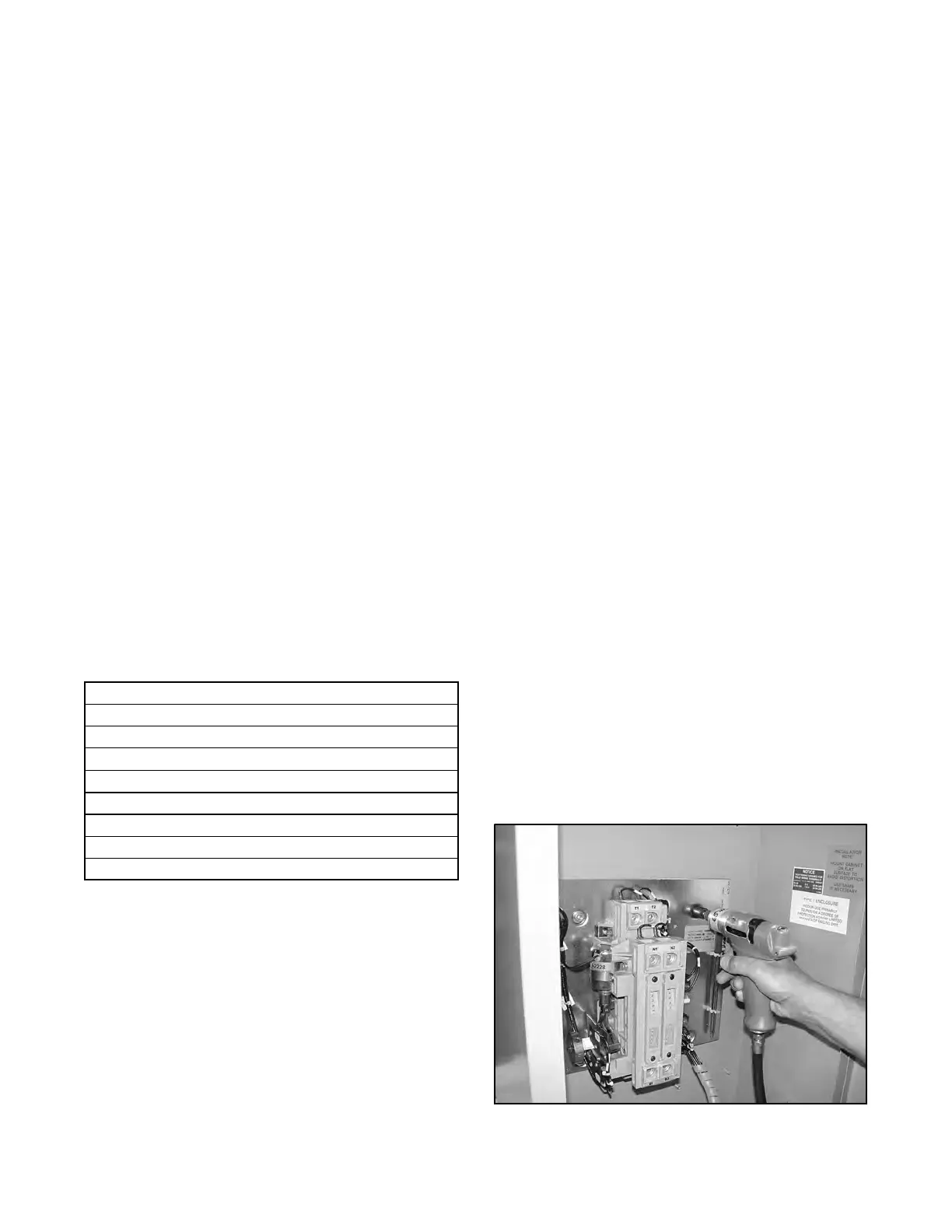
13. Install the new power panel onto the studs in the
back of the enclosure. See Figure 6-6.
14. Fasten the power panel with flat washers, lock
washers and nuts.
15. Torque the nuts to 7.3 Nm (65 in. lb.).
16. Connect the power panel harness to the controller
harness at the inline connector.
17. Connect the load cables to the T terminals.
18. Tighten the connecting bolts to 16.3 Nm (12 ft. lb.).
19. Connect the normal cables to the N terminals.
Figure 6-6 Installing the Power Panel

 Loading...


