TP-6461 1/0892 Section 6, Component Replacement, Model KSS Switches
8. Install the new arc chute.
9. Install the holding screws and washers.
10. Torque screws to 2.8 Nm (25 in. lb.).
11. Manually operate the switch several times to
ensure that it does not stick. See Figure 6-9.
12. Close the enclosure.
13. Reconnect power to the ATS.
14. Enable the generator set.
a. Check that the generator set master switch is in
the OFF position.
b. Reconnect the generator set engine starting
batter(ies), negative (--) lead last.
c. Reconnect the battery charger, if equipped.
15. Move the generator set master switch to the AUTO
position.
16. Test the transfer switch operation by performing
the Automatic Operation Test Procedure described
in Section 4.5.4.
Note: Do not leave the transfer switch in the Test
mode.
Figure 6-9 Manual Operation Handle Inserted
6.5 Limit Switch Assembly
Replacement
Required tools and equipment:
Basic electricians hand tools
Multimeter digital or analog
imit switch
Required protective equipment:
Rubber insulating gloves class 0
Safety glasses
Electrical hazard safety shoes
Procedure
1. Prevent all connected generator sets from starting.
a. Place the generator set master switch in the
OFF position.
b. Disconnect the battery charger, if equipped.
c. Disconnect the generator set engine starting
batter(ies), negative (--) lead first.
2. Disconnect power to the transfer switch.
3. Open the transfer switch enclosure.
4. Verify zero volts across each phase.
5. Note the location of the fast-on connections to the
SCN/SCE microswitch terminals.
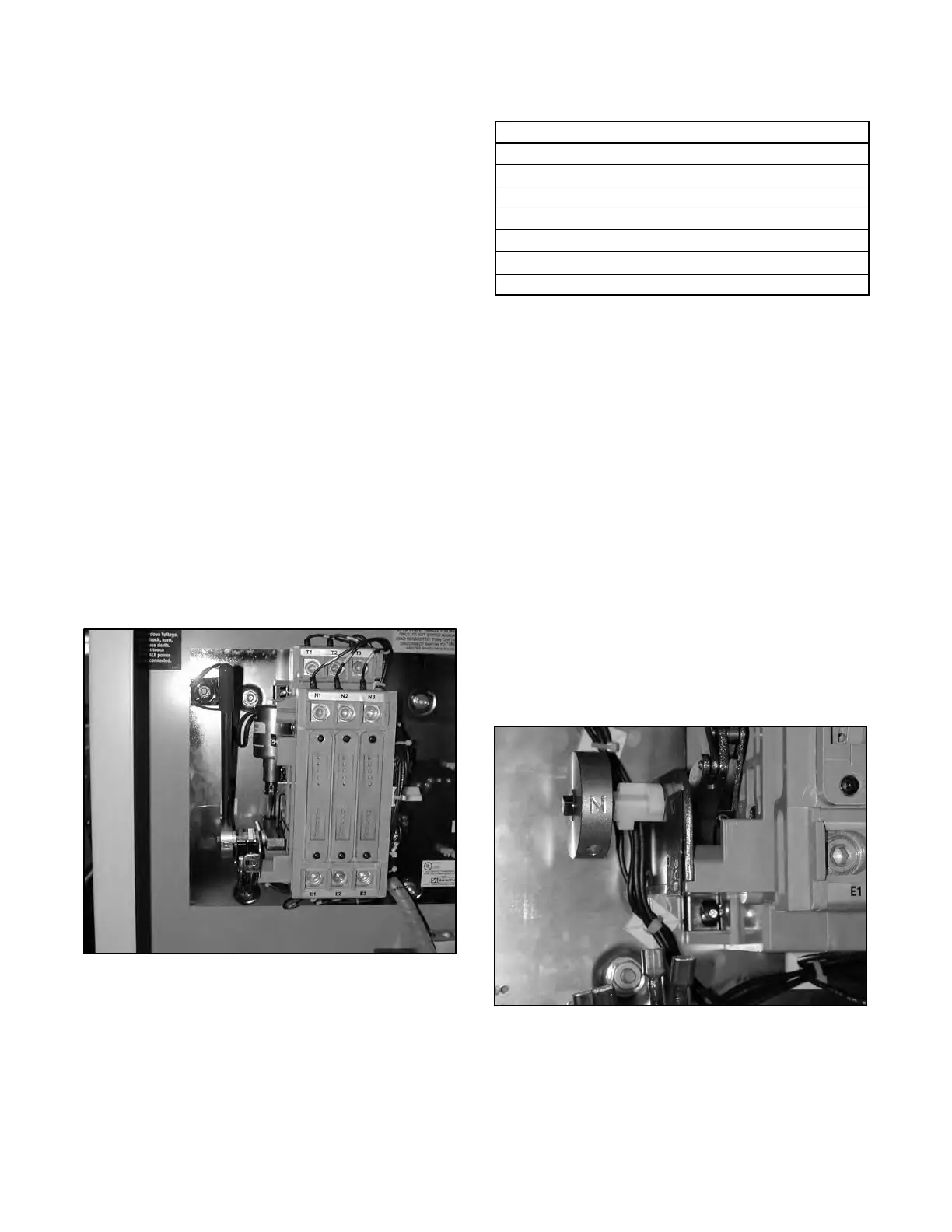
6. Disconnect the fast-on connectors. See
Figure 6-10.
Figure 6-10 Microswitch Fast-On Connectors

 Loading...


