TP-6461 1/08 85Section 5 Component Replacement, Model KGS/KGP
5.3 Auxiliary Switch Removal and
Replacement
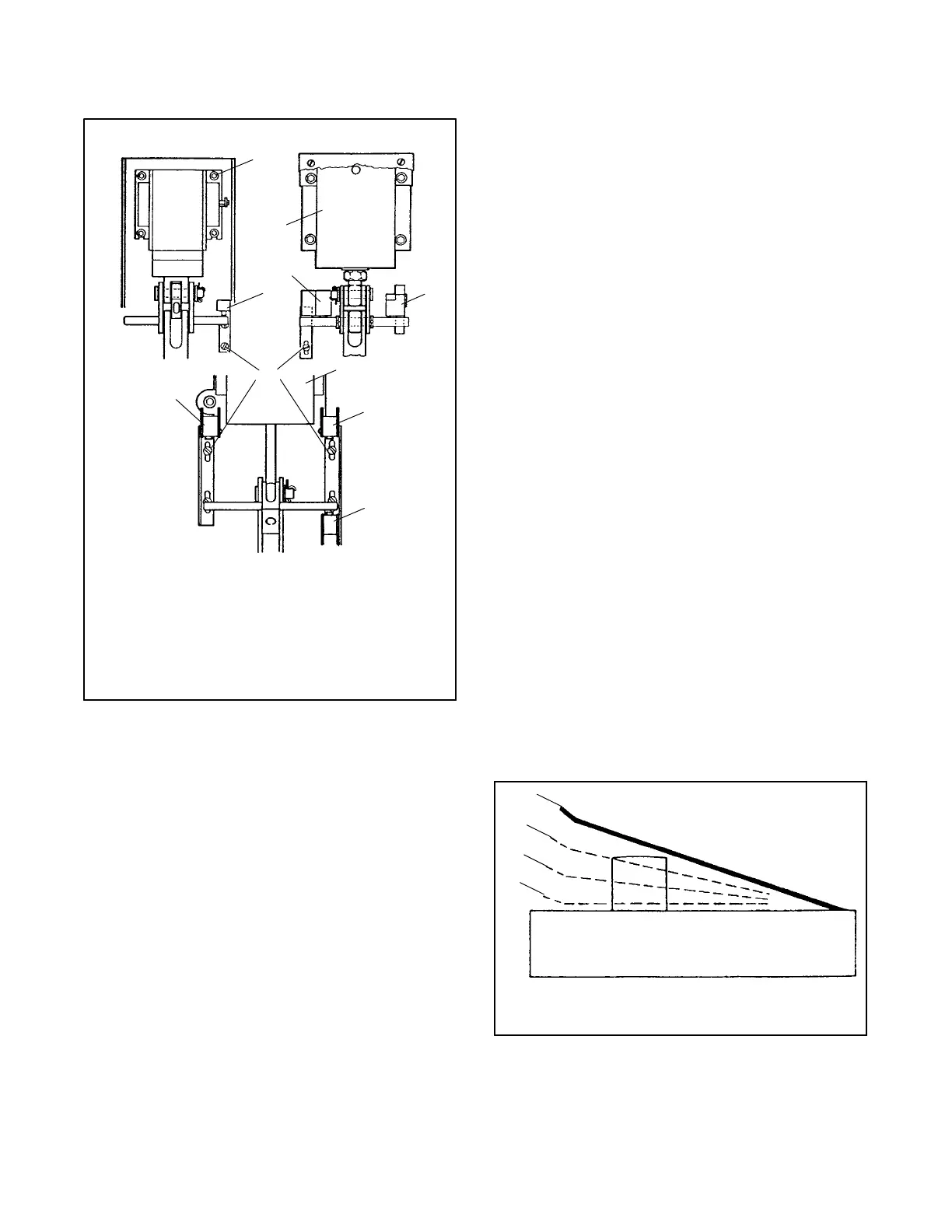
1. 1200 amp 2-position switches
2. 1600--3000 amp 2-position switches
3. SE switches
4. SN switches
5. Mounting screws
6. 1200--3000 amp 3-position switches
7. SNO switches
566865
5
4
3
7
1
2
4
3
6
4
Figure 5-10 Auxiliary Switch
Disconnect both the normal and emergency power
sources from the transfer switch before servicing. If a
generator set provides standby emergency power, turn
the generator set master switch to OFF/RESET and
disconnect the negative (--) battery cable from the set
starting battery.
Removing and Replacing Auxiliary Switch
Assembly
1. Remove the four machine screws, if applicable,
and lift off the metal solenoid cover.
2. Remove the two mounting screws that secure the
bracket-mounted switch assembly to the panel.
3. Before disconnecting the control wiring leads from
the auxiliary switch, observe and note the switch
terminal markings, NO, NC, and C, and which wire
connects to each.
4. Disconnect the wires and connect them to the
corresponding terminals of the replacement switch
assembly.
5. Install the new auxiliary switch assembly with the
two mounting screws.
6. Manually operate the transfer switch to make sure
that the new auxiliary switch trips. Listen for an
audible click when the switch trips.
7. Check the following on the new auxiliary switch:
a. SN/SNO and SE/SEO pairs are adjusted to
have the same over travel.
b. The auxiliary switch trips 1.59 mm (1/16 in.)
before it reaches its fully seated position.
c. After the auxiliary switch trips, there must be
over travel to ensure good switch operation.
d. Do not force the auxiliary switch into the fully
operated position.
e. The auxiliary switches that operate as the main
contacts are closing should trip just as the
contact mechanism reaches the over-center
point.
8. Close the cabinet door.
9. Reconnect the normal power source and
emergency power source. If a generator set is the
emergency power source, connect the negative (-- )
battery cable to the starting battery and place the
generator set master switch in the Auto or Remote
position.
10. Test the switch for proper operation.
1. Full release position
2. Trip position
3. Over travel position
4. Fully operated position
1
2
3
4
566865
Figure 5-11 Auxiliary Adjustment

 Loading...


