TP-6461 1/08
104
Section 7 Component Replacement, Model KSP
7.2.3 Printed Circuit Board
Replacement, 100--400 Amps
Separate the current-carrying unit from the mechanical
unit. See Section 7.2.1.
1. Note the connections (for reconnection later) and
disconnect the printed circuit board leads. See
Figure 7-11 or Figure 7-12.
2. Disconnect the control switch leads at three
terminals. See Figure 7-12.
Note: Hold the terminals while loosening the
screws to avoid damage.
3. Note the connections (for reconnection later) and
disconnect the control switch leads at eight
locations. See Figure 7-13.
4. Remove the bolt and replace the printed circuit
board. See Figure 7-11.
5. Reconnect all leads as noted during step 1.
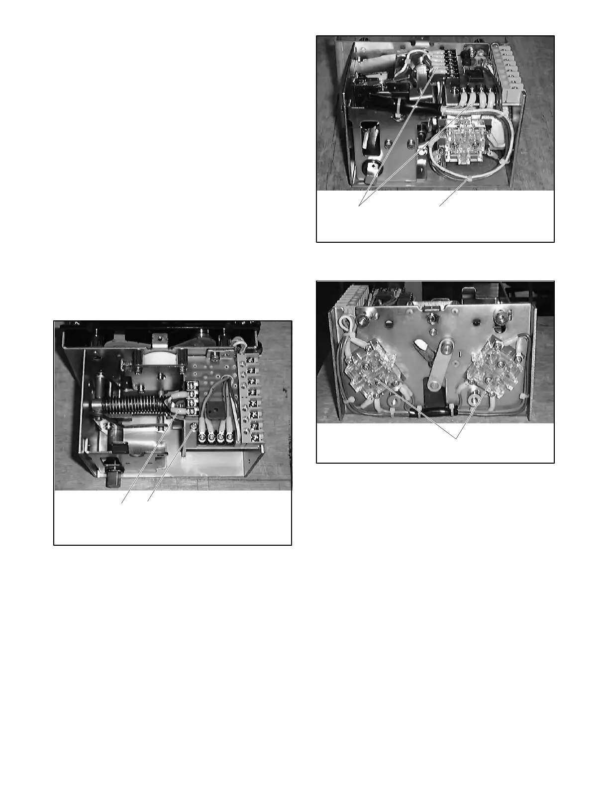
6226
1. Coil leads
2. Bolt
1 2
Figure 7-11 Circuit Board Connections
6226
1. Printed circuit board leads
2. Switch leads
1 2
Figure 7-12 Control Switch Wiring
6226
1. Control switches
1
Figure 7-13 Control Switches

 Loading...


