TP-6461 1/08 55Section 4 Controller Test and Replacement
Section 4 Controller Test and Replacement
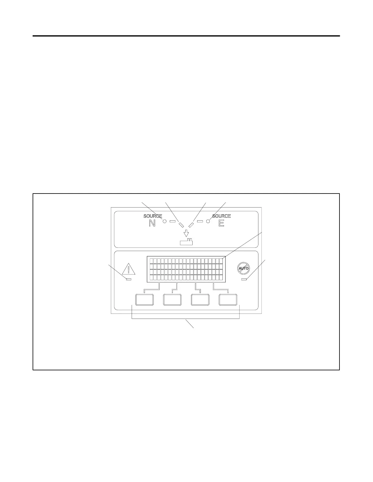
4.1 User Interface Panel
The user interface panel is located on the transfer switch
door. Figure 4-1 shows the user interface pushbuttons
and LED indicators.
4.1.1 Display
The four-line display indicates transfer switch status and
setup, including the following:
D System status
D Faults and warnings
D Active time delays
D Source voltages
D Source frequency (Hz)
D Current (amps)
D Source setup information
D Time and date
D Time and date of next scheduled exercise
The display also identifies the pushbutton functions,
which can change from screen-to-screen.
4.1.2 LED Indicators
LEDs on the user interface indicate contactor position,
source availability, faults, and other conditions.
Figure 4-2 describes the functions of the LED
indicators. See Section 2.7 for more information about
warnings and faults.
1. Source N Available LED
2. Source N Position LED
3. Source E Position LED
4. Source E Available LED
5. Display
6. Not in Auto LED
7. Pushbuttons (4)
8. System Alert LED
GM46892
8
1 2
3
4
6
7
5
Figure 4-1 User Interface Panel

 Loading...


