TP-6461 1/0872 Section 4 Controller Test and Replacement
4.12 File Transfer through the USB
Port
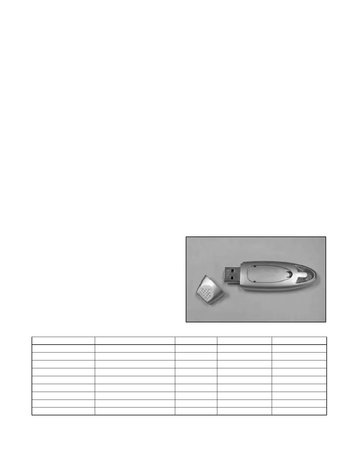
The Universal Serial Bus (USB) port on the main logic
board allows file transfer to and from a USB mass
storage device (removeable drive). Figure 4-17 shows
a typical device. The removeable drive must be
compatible with the USB 2.0 and USB Mass Storage
Device Class specifications.
The controller application code can be updated through
the USB port. Parameter settings, event history, and
other information files can be saved to the storage
device.
The controller recognizes the types of files shown in
Figure 4-18.
4.12.1 Configuration files
The configuration (.cfg) file contains the transfer switch
settings, including:
D System setup
D Source setup, including voltage and frequency
pickup and dropouts
D Time delays
D Inputs and outputs
D Communications settings
D Calibration factors
Configuration files from one transfer switch can be
saved to a mass storage device and then loaded onto
other transfer switches for quick setup of multiple
switches. Serial numbers and descriptions entered
through Monitor III software (or other Modbus
application) are not changed by downloading
configuration files to a transfer switch.
Check the settings and run a test sequence after loading
the configuration file to verify correct operation. Refer to
the ATS Operation and Installation Manual for
instructions to view settings. See Section 4.5 for
instructions to run a test.
Loading Settings when Controller is Replaced
If the controller needs to be replaced, the configuration
file from the old controller (if available) can be loaded
onto the new controller for quick setup.
Note: Operation problems can be caused by incorrect
controller settings. Do not load the old
configuration file onto the new controller unless
you are certain that all the settings in the file are
correct.
Note: When replacing the ATS controller, record the
contactor and ATS serial numbers from the old
controller before removing it, or from the ATS
decals.
Serial numbers are not transferred through the
configuration file and cannot be entered through the
controller’s user interface. Use Monitor III (or a
customer-provided Modbus driver designed for the
system) to enter the contactor and ATS serial numbers
after the new controller is installed. A distributor-level
password is required to enter serial numbers. Refer to
the Monitor III Operation Manual or the Modbus Protocol
Manual for instructions, if necessary. Do not attempt to
change the controller serial number.
Figure 4-17 Typical Mass Storage Device
File name Description Size (approx.) Download to Control Upload to USB
MPAC1500v###.bin Controller application program 950 KB X
MPAC1500_#######.cfg Configuration (parameter settings) 3KB X X
presentyymmdd.his Event history varies X
alarm_settings.alm Common alarms 1KB X
MPAC1500_cal.cal Calibration 1KB X
history_param.hstp Internal use only — X
Param_back.bak Internal use only — X
presentyymmdd.raw Internal use only — X
history_pback.hbak Internal use only — X
Figure 4-18 Recognized File Types

 Loading...


