TP-6461 1/08 83Section 5 Component Replacement, Model KGS/KGP
5.2.3 3000 Amp Model
Removing Contact Assembly, 3000 Amp
Model
Disconnect both the normal and emergency power
sources from the transfer switch before servicing. If a
generator set provides standby emergency power, turn
the generator set master switch to OFF/RESET and
disconnect the negative (--) battery cable from the
generator set starting battery. Locate the generator set
master switch on the generator set control panel.
Note: Replace the B-phase contact assembly only by
first removing two bolts from the adjacent
C-phase contact assembly. Refer to step 7b. for
this replacement procedure.
Refer to Figure 5-1 and Figure 5-8 for the following
procedure:
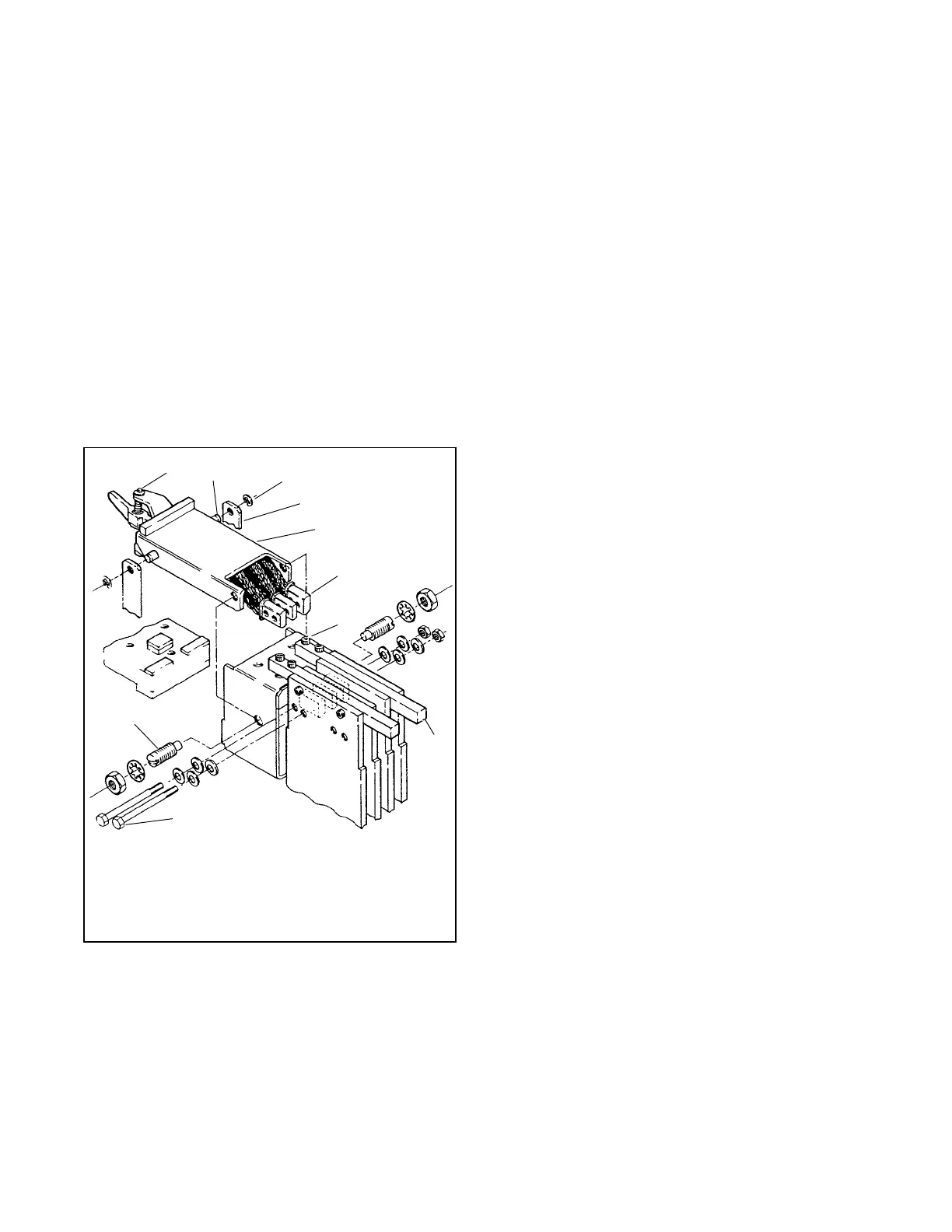
1. .Arc finger adjustment nuts
2. Contact post
3. Retaining rings
4. Actuator arms
5. Contact assembly
6. Braid lug
7. Socket head cap screws
8. Anchor bars
9. Braid lug bolts
10. Pivot studs
566863
3
4
2
7
6
8
9
10
5
1
Figure 5-8 Movable Contact A or C Phase,
3000 Amp
1. Remove the machine screws and flat washers that
secure the blue plastic switch cover.
2. Remove the cover.
3. Remove the screws that secure the arc chute.
4. Remove the arc chute and arc chute pad.
5. Manually place the movable contact assembly that
will be removed in the open position.
6. Remove the two retaining rings and slide the
actuator arms from the contact posts.
7. Remove the twelve 1/4-20 socket head cap screws
from the load bus assembly and lift out the anchor
bars. The longer cap screws are used on the sides.
a. To remove an A-phase, C-phase, or neutral
contact assembly: Remove the bolts, nuts, and
compression washers that secure the braid
lugs to the bus bars. To remove a B-phase
contact assembly follow the procedure
described in step 7b.
b. To remove a B-phase contact assembly:
D Remove the nuts and compression
washers from the ends of the braid lug
studs.
D Remove the nut and washers from the
lower bolt on the C-phase braid lug.
D Remove the bolt.
D Slide the lower B-phase threaded stud into
the hole where the C-phase bolt had been.
D Repeat this procedure with the upper
C-phase bolt and corresponding upper
B-phase stud. Keep the threaded studs in
the C-phase assembly to hold the C-phase
braid lugs in position.
8. Loosen the locknuts and remove the pivot studs.
9. Remove the contact assembly.

 Loading...


