TP-5660 11/9812 Operation
2.3.1 Programmed Transition Switch,
40--260 Amps
Manual Operation Procedure
1. Prevent the generator set, which provides the
emergency power source to the transfer switch,
from starting by moving the generator set master
switch tothe OFF position; disconnecting power to
the generator engine start battery charger, if
installed; and disconnecting all generator engine
start batteries, negative (--) leads first.
2. Disconnect BOTH the normal and emergency
power sources by opening upstream circuit
breakers or switches to the transfer switch.
3. Open the transfer switch enclosure door.
4. Set the disconnect switch (DS) to the INHIBIT
position to prevent the controller from energizing the
solenoid(s). See Figure 2-1.
1
2
4
3
AUTO INHIBIT
EMERGENCY
NORMAL
LOCK
LOCK
5660201
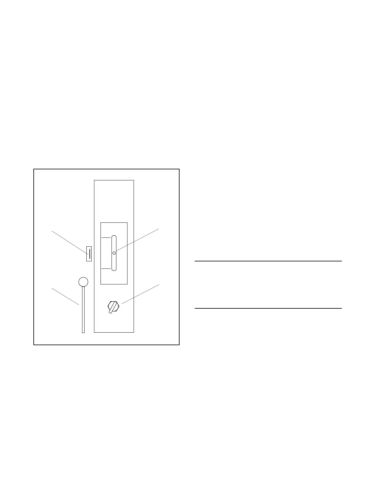
1. Mid-position manual release handle
2. Switch lever, middle (off) position shown
3. Disconnect switch, INHIBIT position shown
4. Manual operating handle, typical
Figure 2-1. Manual Operation, Programmed
Transition Switch 40--260 Amps
5. Attach the manual operating handle to the switch
lever.
6. Ifthehandleisnot inthe middle(off)position,move
thehandleupordowntobringitintothemiddle(off)
position. The switch should operate smoothly
without binding. Both normal and emergency
sources are disconnected from the load in the
middle (off) position.
7. Locate the mid-position manual release handle on
the left side of the switch. See Figure 2-1.
8. Pull and hold the mid-position manual release
handle to the left. This releases the mechanism
that allows manual switching to the normal or
emergency source from the off position. Move the
handle up to the normal position to manually
connect the load to the normal source or down to
the emergency position to manually connect the
load to the emergency source. The switch should
operate smoothly in both directions without
binding.
9. Manuallyconnect the load tothe normal sourcefor
automatic operation.
10. Remove and return the manual operator handle to
the holder provided.
11. Move the disconnect switch (DS) to the AUTO
position for automatic operation.
12. Close and lock the transfer switch enclosure door.
13. Reconnect power supplies to the transfer switch.
NOTE
Wheninitiallyapplyingpowertothetransferswitch,
the engine start contacts remain closed signalling
the generator to run until the ATS’s Time Delay
Engine Cooldown (TDEC), if equipped, ends.
14. Reconnect generator engine start battery cables,
negative (--) leads last; reconnect power to the
generator engine start battery charger, if installed;
and move the generator set master switch to the
AUTO (automatic) position. The generator may
start and run for a while (see NOTE above).
 Loading...


