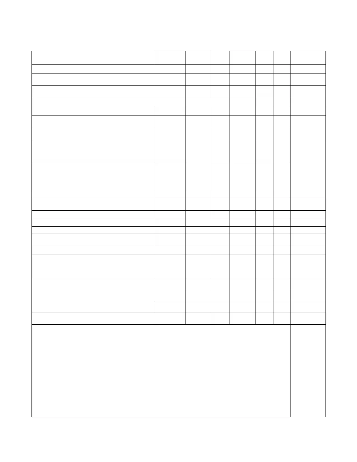
TP-5660 11/9820 Scheduled Maintenance
4.3 Service Schedule
Follow the service schedule below for the recommended service intervals. Have all service performed by an
authorized service center except for activities limited to the items designated by an X.
System Component or Procedure
See
Section
Visually
Inspect
Check Change Clean Test
Frequency
ELECTRICAL SYSTEM
Check for signs of overheating or loose connections:
discoloration of metal, melted plastic, or a burning odor
4.1.1 X X M
Check the contactor’s external operating mechanism
for cleanliness and clean and relubricate if dirty *
4.1.1 X
D, R
(lubricant)
D M
Check wiring insulation for deterioration, cuts, or
4.1.1 X
M
properties of the original wiring
4.1.2 D D
(wiring)
Q
Check the transfer switch’s main power switching
mechanisms’ mechanical operation and integrity
4.1.2 D D D Y
Tighten control and power wiring connections to
specifications
4.1.2, 6.4, L D D Y
Check the transfer switch’s main power switching
contacts’ condition and clean or replace the main
contacts or replace the contactor assembly as
necessary
4.1.2 D D, R D Y
Perform a thermal scan or millivolt drop test to check
for high contact resistances on power circuits. Tighten
connections, clean main contacts, adjust or replace
main contacts or contactor assembly to eliminate high
contact resistances
4.1.2 D D, R D D Y
Test wire and cable insulation for electrical breakdown 4.1.2 D Every 3 Years
Check calibration of voltage-sensing circuitry and
setpoints, and recalibrate circuitry as necessary
4.1.2 D D Every 5 Years
CONTROL SYSTEM
Exercise the generator set under load 4.2.1, L X W
Test the transfer switch’s automatic control system 4.2.2, L X X M
Test all indicators (incandescent lamps and LEDs) and
all remote control systems for operation
L D D D, R D Y
GENERAL EQUIPMENT CONDITION
Inspect the outside of the transfer switch for any
condition of vibration, leakage, noise, temperature,
contamination, or deterioration to keep the transfer
switch clean and in good condition *
4.1.1 X X W
Check that all external hardware is in place, tightened,
and not badly worn
4.1.1 X X R W
Inspect the inside of transfer switch for any condition of
4.1.1 X X D M
or deterioration to keep the inside of the transfer switch
clean, dry, and in good condition *
4.1.2 D D D Y
Check that all internal hardware is in place, tightened,
and not badly worn
4.1.2 X D M
* Service more frequently if operated in dusty or dirty areas.
See Section Read these sections carefully for additional information before attempting maintenance or service.
Visually Inspect Examine these items visually.
Check Requires physical contact with or movement of system components, or the use of nonvisual indications.
Change May require replacement of components depending upon the severity of the problem.
Clean Removeaccumulationsofdirtandcontaminantsfromexternaltransferswitch’scomponentsorenclosurewithavacuum
cleaner or by wiping with a dry cloth or brush. Do not use compressed air to clean the switch because it can cause debris to
lodge in the components and cause damage.
Test May require tools, equipment, or training available only through an authorized service center.
L See the transfer switch logic controller operation and installation manual for more information.
D Have service performed by an authorized service center.
X Operator action.
R May require replacement of components.
W=Weekly
M=Monthly
Q=Quarterly
S=SixMonths
Y=Yearly
 Loading...


