TP-5660 11/9856 Installation
6.1.3 Unpacking
Unpack the transfer switch immediately after receipt
and inspect for shippingdamage. Failure to perform an
immediate inspection impedes recovery of losses
causedbyshippingdamage. Usecarewhenunpacking
to avoid damaging any of the transfer switch
components. Remove all dirt and packing material that
mayhaveaccumulatedinthetransferswitchoranyofits
components.
If the equipment has been stored at cold temperatures,
allow equipment to warm to room temperature for
24 hours (minimum) before unpacking to prevent
condensation on the electrical apparatus from
surrounding moist air.
6.1.4 Storage
Store the transfer switch in its protective packing until
ready for final installation. Protect the automatic
transfer switch at all times from excessive moisture,
construction grit, and metal chips. Avoid storage in low
temperature and high humidity areas where
condensation could occur on the unit.
6.2 Mechanical Installation
Check the System Voltage and Frequency Do not
install a transfer switch if the system voltage and
frequency shown on the transfer switch nameplate are
differentfrom thenominalnormal(utility)sourcevoltage
and frequency and the nominal emergency source
voltage and frequency shown on the generator set
nameplate.
To plantheinstallation,usethe dimensionsgiven onthe
enclosure dimension drawings in Section 5. Select the
mounting site to comply with local electrical code
restrictions for the enclosure type. Mount the transfer
switch as close to the load and power sources as
possible. Allow adequate space to open the enclosure
door fully and to service the switch.
Vertically mount the 40- through 260-ampere transfer
switches covered in this manual to a wall or other rigid
vertical supporting structure. Keyhole slots for
mounting purposes are provided in the mounting
brackets on the top and bottom of each unit. When
mounting these units, plumb the enclosure to ensure
thatthedoorhingesareverticaltoavoidanydistortionof
the enclosure or door. Place washers behind the
mounting bracket key holes to shim the enclosure to a
plumb condition.
Floor mount or attach the 400-ampere transfer switch
covered in this manual to a rigid supporting structure
such as a wall. When mounting these units either way,
plumb the enclosure to ensure that the door hinges are
vertical to avoid any distortion of the enclosure or door.
For floor mounting, bolt the mounting feet to the floor
and shim the mounting feet as needed to plumb the
enclosure. Keyholeslotsfor wallmountingareprovided
intherearpaneloftheenclosure. Placewashersbehind
themountingbracketkeyholes toshimthe enclosureto
a plumb condition.
Bolt the 600- through 3000-ampere automatic transfer
switches directly to floor mounting pads. When
mountingone of theseunits,level the mountingpads so
that the door hinges are plumbwhen the unit isinstalled
to avoid distorting the enclosure or door.
6.3 Check Manual Operation
Follow a procedure in Section 2.3 to manually operate
thecontactorbut stopbeforereapplyingpowersources.
Verify that the contactor operates smoothly without
binding and prepare it for automatic operation. If the
contactor does not operate smoothly without binding,
STOP! Call an authorized service center to service the
contactor before proceeding!
6.4 Electrical Wiring
All internal electrical connections are prewired. The
onlywiringnecessarywheninstallingthetransferswitch
is to connect the unit to external devices.
Observe all applicable national, state, and local
electrical codes during installation.
Install DC, control, and communication system wiring
in raceways, cables, or conduit separate from AC
power wiring.
See Section 5 for schematic diagrams and enclosure
drawings.
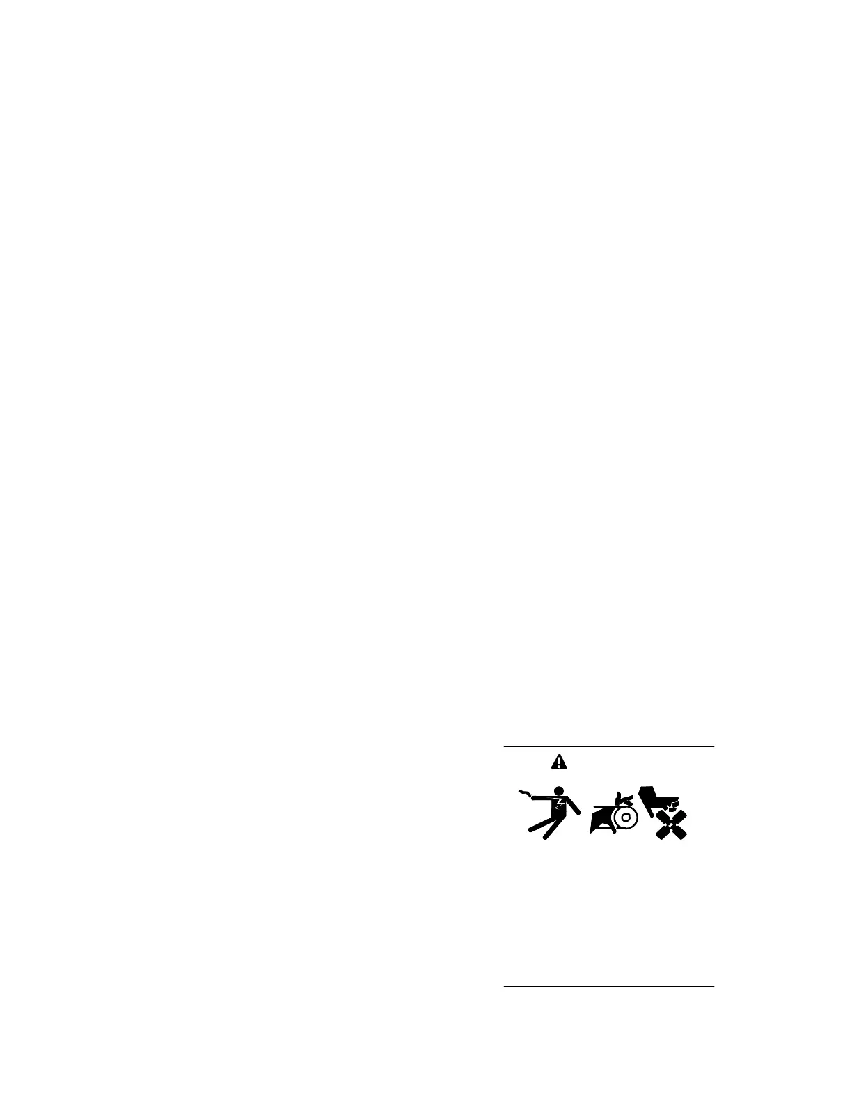
Accidental starting.
Can cause severe injury or death.
Disconnect battery cables before
working on generator set. (Remove
negative (--) lead first when
disconnecting battery. Reconnect
negative (--) lead last when
reconnecting battery.)
WARNING
 Loading...


