TP-5660 11/98 Specifications 1
Section 1. Specifications
1.1 Purpose
An automatic transfer switch (ATS) transfers critical
electrical loads from a normal (preferred) source of
electrical power to an emergency (standby) source
when the normal source fails to maintain minimum
voltage and/or frequency levels.
Upon normal source failure, the ATS signals the
generator set to start. When the emergency source
reaches a minimum voltage and/or frequency level, the
ATS transfers the load from the normal source to the
emergency source. The ATS continuously senses the
normalsource andtransfers theload backto thenormal
sourcewhenthenormalsourcereturns. Aftertransferof
theloadbacktothenormalsource,theATSremovesthe
generator set start signal, allowing the generator set to
shut down.
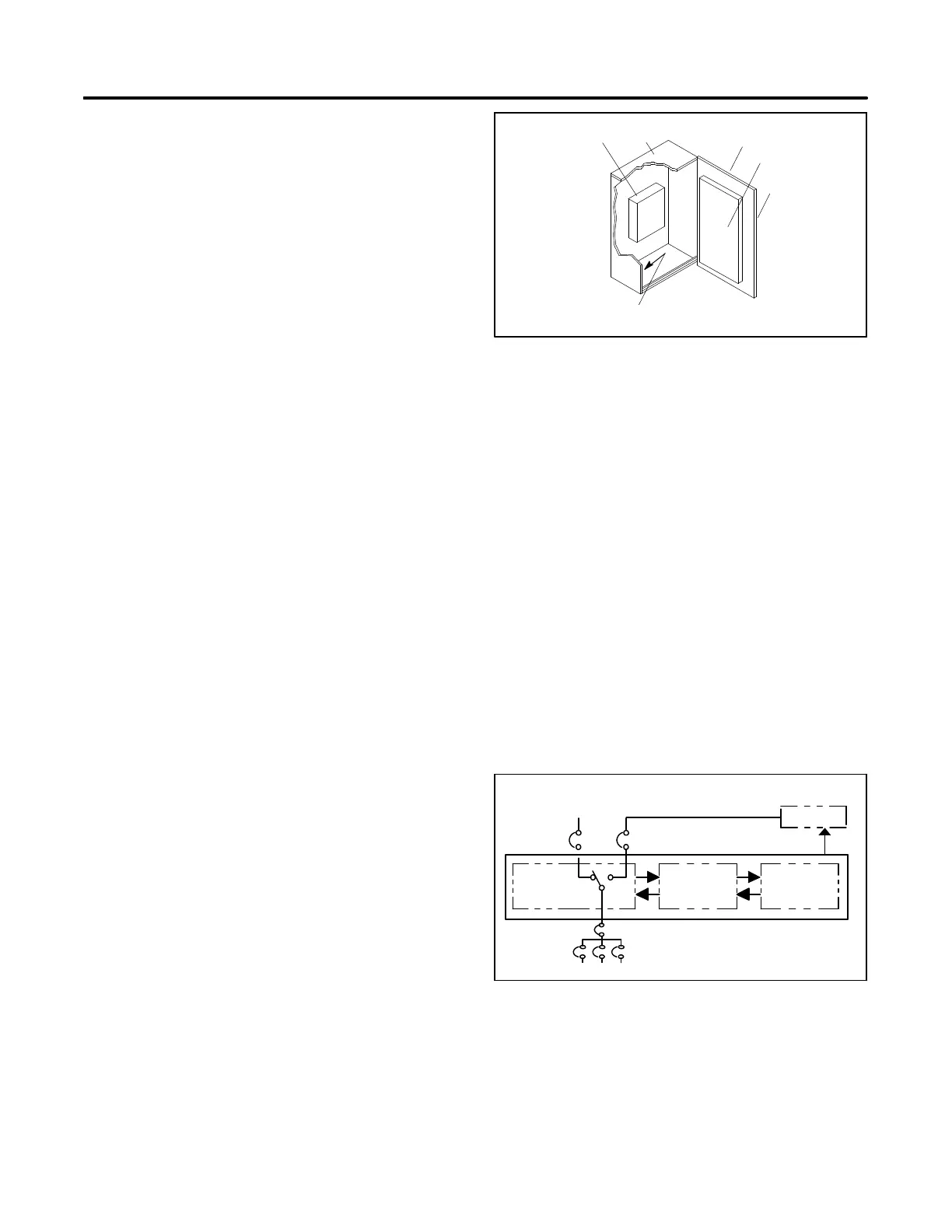
1.2 Components
A typical transfer switch consists of functional units
mounted in an enclosure with a hinged front door. See
Figure 1-1. The power switching device connects the
load to the normal or emergency sources of power. An
inner panelmounted on theinside of theenclosure door
containsthe electrical controls(logic controller)circuitry
that monitors power sources, controls the power
switching device, and signals the generator to start
when needed. Enclosure door-mounted controls and
indicators allow the operator to control the transfer
switch operation mode and obtain system status
information. A wire harness with inline connectors to
facilitate component replacement and door removal
connects the inner panel to the power switching device.
Controls and indicators on the transfer switch are
determined by the logic controller and installed
accessories. For details see the operation and
installation manual for the logic controller specified by
the part number model code on the transfer switch
nameplate. See Sections 1.3 and 1.4 to determine the
logic controller on the transfer switch. See List of
Related Materials in the Introduction section in this
manual.
1
4
TS-001
6
2
3
5
1. Power switching device
2. Enclosure
3. Enclosure door
4. Inner panel electrical controls (logic controller)
5. Controls and indicators (mounted on enclosure door)
6. Neutral lug
Figure 1-1. Typical Transfer Switch Components
The power switching device transfers power from the
normal or emergency power source to the load. See
Figure 1-2. The controller electrically actuates the
power switching device to select a power source, and
theswitch mechanicallylatches intheselected position.
The switch also includes a provision for manual
mechanical operation in emergency nonpowered
conditions. Within the switch are two sets of multipole
contacts. One set of contacts selects power from the
normal source and the other set selectspower from the
emergency source. The two sets of contacts are
mechanically interlocked within the switch, ensuring
that only one set of contacts is closed simultaneously.
Mechanical interlocking ensures load servicing without
cross-coupling of the power sources.
Interface
Power
Switching
Device
To Load
Automatic Transfer Switch
Logic
Controller
Normal
(Utility)
Power
Emergency
(Generator)
Power
Generator
Start Generator
TS-002
Figure 1-2. Typical Transfer Switch Block Diagram
 Loading...


