too high. Lower the high probe or raise the low probe slightly, until proper operation is
evident.
WATER LEVEL ASSEMBLY (FLOAT TYPE) INSTALLATION INSTRUCTIONS
DOCUMENT #307 1054 01
REMOVE OLD WATER LEVEL PROBES, WIRE HARNESSES AND CONNECTORS
Remove the old water level probe assembly, wire harnesses and connectors from the control box all the way to the
water level tube on the water plate. Start in the top right corner of the control box. On the PC board, there is a small
black connector with black, white and red wires. Un-clip it and remove it thru the hole in the top/back of the control
box. Remove all connected wire harnesses & connectors all the way to the water level tube on the water tank. Note
which way the wiring is routed, for installation of the new water level probe assembly. You may cut out the wiring &
connectors from the old water level probe assembly as needed. All new wire harnesses and connectors will be
supplied with the new water level probe assembly.
CONNECT NEW WATER LEVEL PROBE, WIRE HARNESSES AND CONNECTORS
1. In the replacement kit, find the harness with the small black connector on one end. Feed the black connector thru
the hole in the control box and plug it into the PC board. The terminals on the other end of the harness will be
connected in step 3 below.
2. Place the new probe with the correct float setup (see FLOAT SETUP below) into the water tube and hang it back
onto the top edge of the water tank. Run the other end of the probe wire harness thru the machine to near the back of
the control box.
3. Connect the terminals on the ends of the black, white & red wires to the terminals on the ends of the black, white &
red wires on the harness you installed into the control box in step 1 above, being sure wire colors correspond for each
connection.
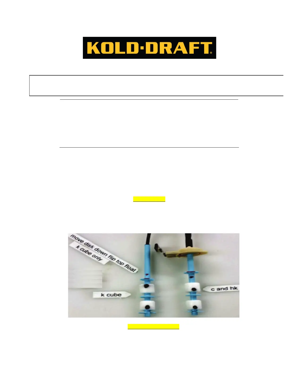
FLOAT SETUP
In order for the probe switches to correctly work for K CUBE machines the top float must be flipped over so the
magnetic strip is on top. The round blue disk above the top float must also be moved down to the empty grove below
it. Both the K and C/HK setups are shown in the picture below. The black dots indicate where the magnetic strip is. If
you are unsure where the magnetic strip is located, hold the float up to a light source and the magnetic ring will be
more easily identified.
FLOAT ADJUSTMENTS
In order for the machines to make a solid cube some adjustments may be needed. If the ice being harvested is too light or does not
have the right dimple size to make it solid, the entire probe will need to be raised slightly. This can be done by grabbing the probe
at the top and pulling slightly. If the ice is too solid and there is no dimple in the ice cube then the probe needs to be lowered.
Grabbing the probe at the top and pushing it in will lower it. Raise or lower the probe for right ICE CUBE QUALITY Proper
adjustment of the control stream and water level probes will produce ice cubes containing a 1/8" to 3/16" dimple.
CAUTION! RISK OF PERSONAL INJURY, PROPERTY DAMAGE, EQUIPMENT FAILURE OR FIRE
Refer all maintenance to qualified personnel. Disconnect power before servicing equipment.
Read and understand all instructions before proceeding.