K5 Plus GNSS
- 12 -
③ Screw hole: fix the mainframe to the tribrach or the pole
④ Beeper: broadcast voice messages
⑤ UHF/GPRS socket: connect UHF/GPRS antenna
⑥ 5-pin cable socket: connect power cable
⑦ 7-pin data cable socket: connect data cable
5-pin interface: for connecting to the external Radio or external power;
7-pin serial port: used to connect to computer to transfer data, or handheld;
GPRS interface: Install the GPRS (GSM/CDMA/3G optional) network antennas;
UHF interface: Install UHF radio antenna;
§2.1.3 Indicator panel
a) K5 PLUS mainframe indicator has two meanings:
The indicator for mode switching and working modes;
The indicator for mainframe self-check status;
b) In order to let you have a better understanding of the specific meaning of the
indicator in the two status, we will describe in detail.
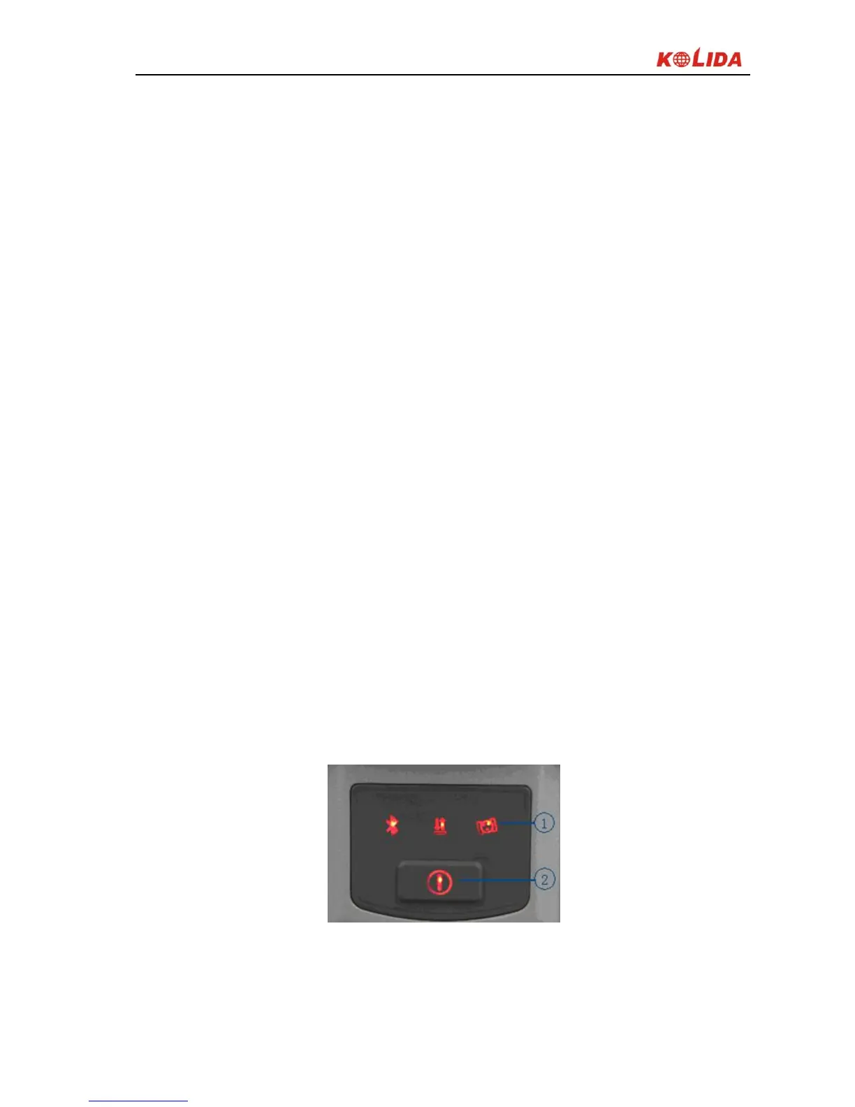
K5 PLUS indicator panel has been re-designed with 3 LED indicators, simply
and clearly indicates the various status, as shown below:
Figure 2-5
①3 indicator lights ②Power key
The following are the meanings of some typical lights: