Payload Meter III - Section 60 OM6009 8/11
Page 60-2
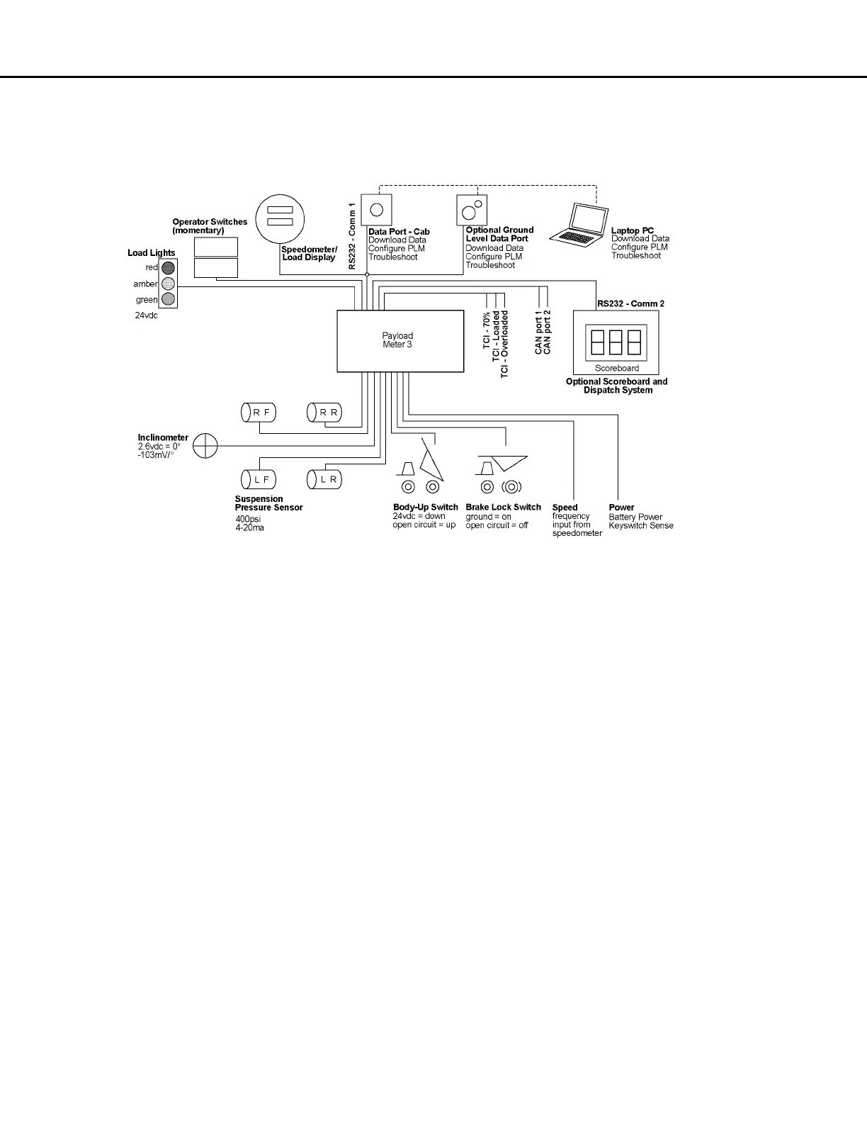
COMPONENT DESCRIPTION
System Diagram
Suspension Pressure Sensors
PLMIII uses a two-wire pressure sensor. The range
for the pressure sensor is 281 kg/cm
2
(4000 psi) and
the overload limit is 700 kg/cm
2
(10,000 psi). One
wire to the sensor is the supply voltage and the other
is the signal. The 0 - 281 kg/cm
2
(0 - 4000 psi) range
is converted into an electrical current between 4 and
20 ma. The supply voltage for the sensor is nominally
+18VDC. Each pressure sensor has an 3000 mm
(118 in.) length of cable. The cable is specially
shielded and reinforced to provide mechanical
strength and electronic noise immunity.
Inclinometer
The inclinometer is used to increase the accuracy of
load calculations on an incline. The inclinometer
uses three wires. For the sensor, red is the +18VDC
supply voltage, black is ground and the white is the
signal. The incline signal is a voltage between 1 and
4 volts. Zero degrees of incline is represented by
2.6VDC on the signal line. The voltage signal will be
decreased by 0.103VDC for every degree of nose up
incline.
Speedometer/Load Display
The speedometer/load display is used as a
speedometer and as a payload information display.
The top display is used for speed and can display
metric (kph) or English (mph) units. See “Digital
Display Operation” in Section 32 for instructions on
setting the displayed units. The speedometer can be
adjusted using a calibration potentiometer in the
back just like existing speedometers.
The payload meter uses the lower display for
payload information. The normal display mode
shows the current payload. The display can be
changed to show the load and total tons counter or
the Operator ID. Using the operator switches on the
dash panel, the current suspension pressures and
incline can be displayed. The units for display are set
using the PC software. Payloads can be displayed in
short tons, long tons or metric tons.
 Loading...


