Operation - Section 32 OM3223
Page 32-4 Operator Cab and Controls
HEATER / AIR CONDITIONER
COMPARTMENT AND CONTROLS
The heater/air conditioner compartment contains
heater/air conditioner controls (6, Figure 32-1) and
the heater/air conditioner components, such as the
blower motor assembly and heater coils. Optimum
cab air climate can be selected by using the following
controls in various combinations.
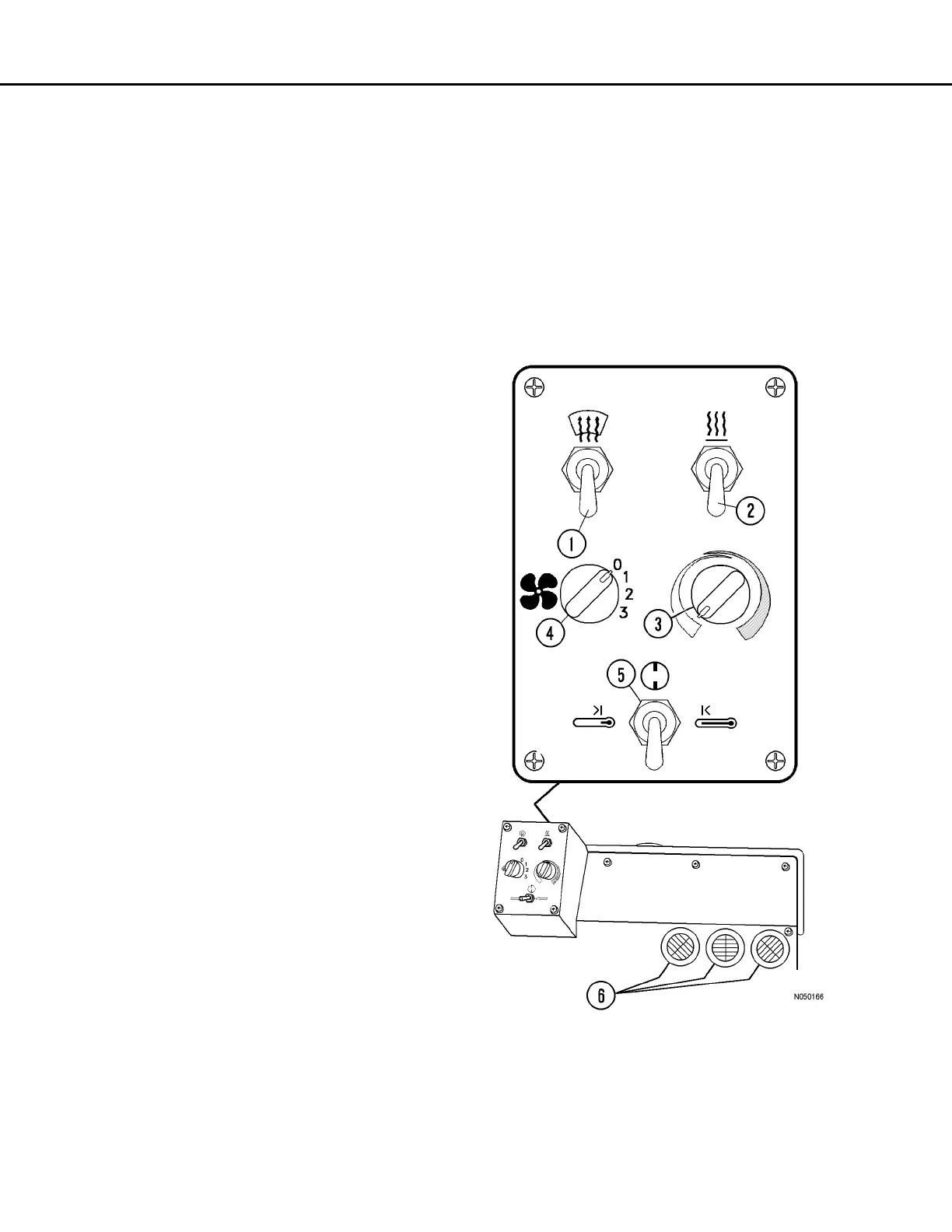
Defroster Vent Control Switch
Defroster control switch (1, Figure 32-5) directs
heated air for windshield defrosting. The down posi-
tion of the toggle switch is off. The up position of the
toggle switch is on.
Heat Control Switch
Outside/inside air control switch (2, Figure 32-5)
allows either outside or inside air to be circulated
through the cab heater assembly.
Moving the switch up directs outside air to be circu-
lated through the heater assembly and through the
cab.
Moving the switch down directs inside air to be recir-
culated through the heater assembly.
Temperature Control Knob
Temperature control knob (3, Figure 32-5) is pro-
vided for the operator to select a comfortable temper-
ature.
Rotating the knob counter-clockwise (blue arrow) will
select cooler temperatures. Full counter-clockwise
position is the coldest air setting.
Rotating the knob clockwise (red arrow) will select
warmer temperatures. Full clockwise position is the
warmest heater setting.
Fan Control Knob
Fan control knob (4, Figure 32-5) is provided to con-
trol the cab air fan motor. The fan motor is a three-
speed motor (low, medium and high). Speeds are
selected by rotating the control knob clockwise to the
desired position. The OFF position is full counter-
clockwise position.
Heater / Air Conditioner Selector Switch
Selector switch (5, Figure 32-5) allows the operator
to select heat or air conditioning, or neither. The left
position of the switch activates the air conditioning
and the right side of the switch activates the heater.
Neither the heat nor the air conditioning can be acti-
vated in this position.
Heater / Air Conditioner Vents
These heater/air conditioner vents (6, Figure 32-5)
may be rotated 360°. Air flow through the vents is
controlled by manually opening/closing or turning the
louvers.
FIGURE 32-5. A/C HEATER CONTROLS
1.Defroster Control
2.Outside/Inside Air
3.Temperature Control
4.Fan Control Knob
5.Selector Switch
6.Vents