31
Connection
The combi-cleaner may be advantageously instal-
led to allow crop passage immediately after intake
and before discharge.
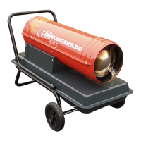
Location
Place th combi-cleaner so as to allow space beside
the unit for necessary adjustments.
Do not forget to provide space for screen replace-
ment, i.e. about 1.5 m beside the unit. Screen re-
placement is most easily done from the right-hand
side of the combi-cleaner (viewed from the inlet
end).
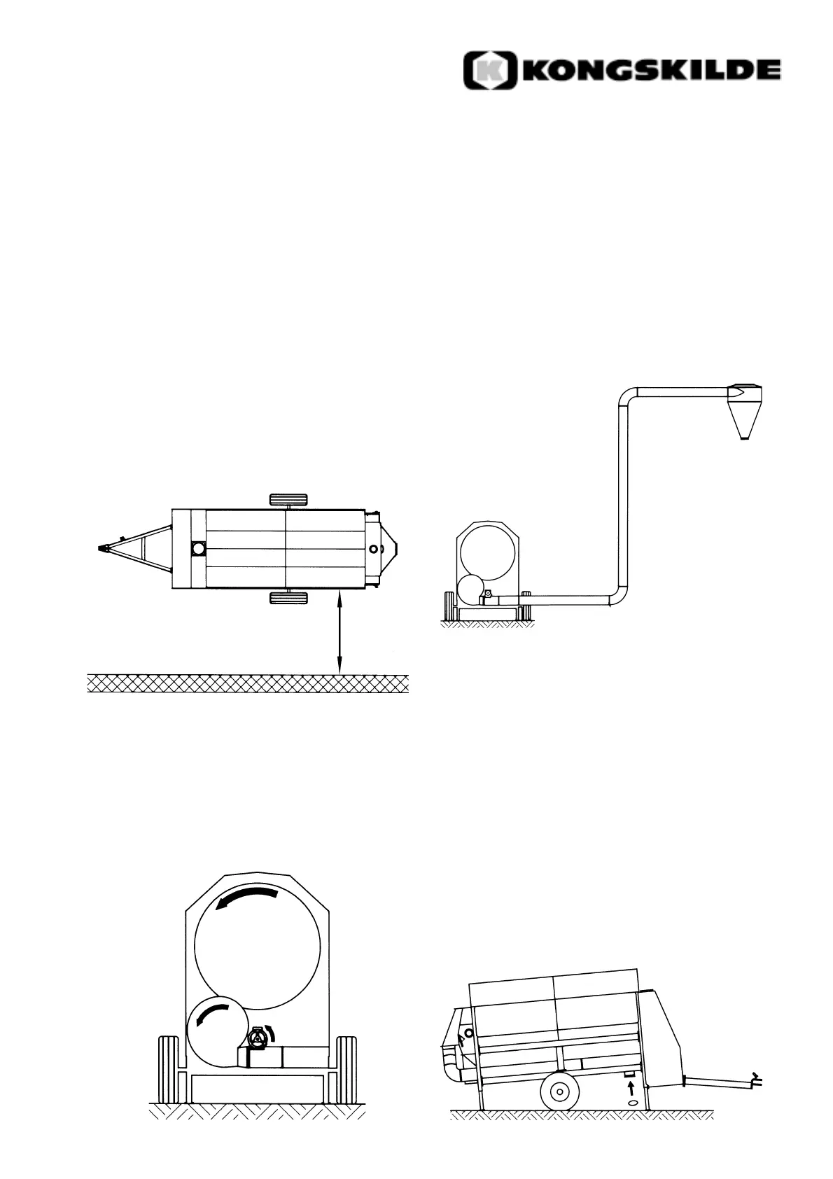
Direction of rotation
Wiring should be made for counter-clockwise
direction of rotation of screen drum, fan and trough
auger (viewed from the inlet end).
Pipeline for fan
The fan pipeline should be of the OK200 dimensi-
on. It is recommended to use as few bends as pos-
sible and a cyclone at the end of the pipeline.
At a commonly occurring content of impurities in
the crop the fan is powerful enough to blow the
trash approx. 20 m (including 4 m vertical lenght,
two bends and one cyclone).
If to much fan power is applied to conveying, this
will reduce the air flow and, accordingly, the
cleaning efficiency of the aspiration cleaner. If
additional conveying length is required, an extra fan
may be inserted.
Separation of screenings
The screenings may either be disharged through a
separate gravity outlet or delivered into the trash
blow line and discharged together with the light
impurities.
Impurities separated by screens and aspirator
disharged into the trash blow line: Mount the
covering plate in the outlet of the trough auger.
1,5 m
90°
90°
4 m
Cyclone
OK200 pipe
system