14
About Measuring Probe
Setting a Measuring Probe
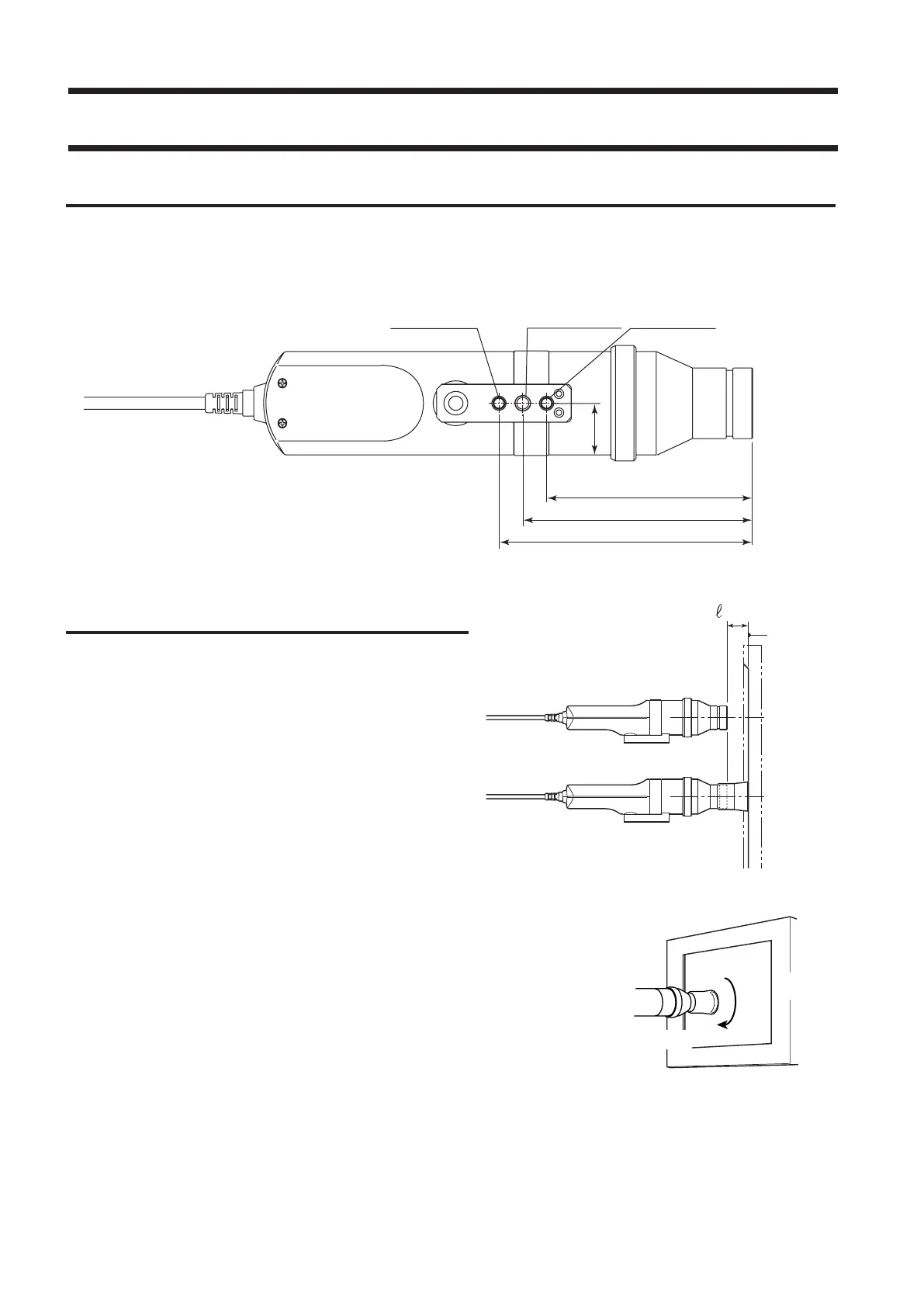
Two types of screw holes are provided to secure the measuring probe.
Tripod screw hole: Used to mount the probe to a tripod. The screw hole depth is 6 mm.
ISO screw hole: Used to mount the probe to a jig. An ISO screw (5 mm, depth: 6 mm) can be used.
Setting the Measuring Distance
1
. Secure the display to be measured.
2
. Set the pointing ring to the MEAS position.
3
. Make sure that the distance from the
display surface to the tip of the probe is
30 mm, and secure the probe.
Make sure that the probe is placed perpendicular to the
display surface.
<Caution>
• When measuring displays which have a high level of view angle
dependability, measurement reproducibility will be higher if the
installation angle θ of the measuring probe is kept constant for all
measurements.
• Use of the hood (standard accessory) not only prevents entry of envi-
ronmental light but also makes it easy to place the instrument at the
specied distance and perpendicular to the object.
• LED Universal Measuring ø27 Probe(CA-PU32/35), LED Flicker
Measuring ø27 Probe(CA-P32/35)
: The stated accuracy remains valid when ℓ is in the range of 30 mm
±10 mm.
• LED Universal Measuring ø10 Probe(CA-PSU32/35), LED Flicker
Measuring ø10 Probe(CA-PS32/35)
: The stated accuracy remains valid when ℓ is in the range of 30 mm
±5 mm.
Display’s
screen
surface
(When used with the hood)
(When used without the hood)
ISO screw hole ISO screw hole
Tr ipod screw hole
88 mm (116)
22 mm
98 mm (126)
108 mm (136)
*( )Measuring Ø10 Probe
Measuring Probe
Display
θ