®
(j)
r
-,,---
--,
1MIDll
1CONTRAST1
I
It
I
I
11
• • • I
I
l/•o·•
r O
11
•
·:
L
__
J I
0 0
I
L-~--·-
.J
VALUE
...
0
..
.
. .
' .
' .
. .
.
r-------
------,
l I
NT
CARD
:
I
<==J
c::=2'
~
==-=-====::.---------~
1
COMBI
EDIT
COMBI :
:<==J
c=J:
I I
I
PROG
EDIT
PROG
I
:<==Jc=]:
:
SEQ
GLOBAL :
l<==J
~:
t_
____________
.J
--'----
_:e~~-,
I
START/STOP
: I
REC
I
:<==]::~:
L.;
__
--~'---
---'
~--------------,
: Q 5 I
i<==J
c=J:
: l 6 :
:<==]
c=J:
: 2 7 :
1<==J
c=]:
I J 8 :
i<==J
c=J:
: 4 9 :
:<==J
c=J:
f
~~~~R~.:-~:~-~~-;o~c=:
:<==J:~c=::):
·---
__
11
___
--~
MIR
I MUSIC WORKSTATION
[I]
I
POWER
OWN
--~--·
KORG
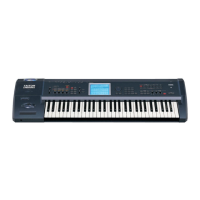
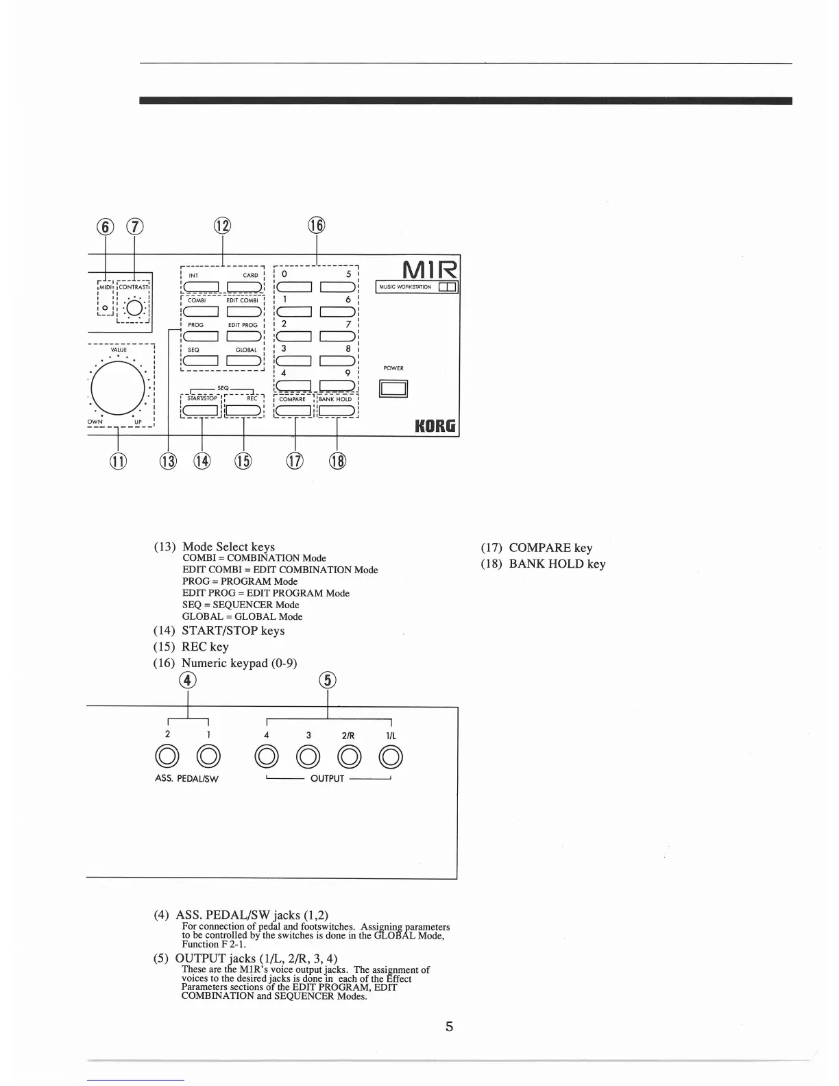
(13) Mode Select keys
COMB!=
COMBINATION Mode
EDIT COMB! = EDIT COMBINATION Mode
PROG = PROGRAM Mode
EDIT PROG
=EDIT
PROGRAM Mode
SEQ =SEQUENCER Mode
GLOBAL= GLOBAL Mode
(14) START/STOP keys
(15) REC key
(16) Numeric keypad (0-9)
© @
2
4
3
2/R
l/L
ASS.
PEDAL/SW
L___
OUTPUT
----'
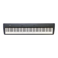
(4) ASS. PEDAL/SW jacks (1,2)
For connection
of
pedal and footswitches. Assigninglarameters
to be controlled
by
the switches is done
in
the GLOB L Mode,
Function F 2-1.
(5) OUTPUT jacks (1/L, 2/R, 3, 4)
These are the
Ml
R's
voice output jacks. The assignment
of
voices to the desired jacks
is
done in each
of
the Effect
Parameters sections
of
the EDIT PROGRAM, EDIT
COMBINATION and SEQUENCER Modes.
5
(17) COMPARE key
(18) BANK
HOLD key