Do you have a question about the Korg X3 and is the answer not in the manual?
Instructions for removing the bottom plate of the unit.
Steps to remove the main board (KLM-1645) from the unit.
Procedure for removing the analog board (KLM-1648) from the unit.
Steps for removing the power supply unit assembly.
Procedure for removing the floppy disk drive assembly.
Instructions for removing the LCD unit from the unit.
Steps for removing the panel boards (KLM-1647/16478).
Procedure for removing the keyboard from the unit.
Steps for removing the joystick assembly from the unit.
Procedure to activate the diagnostic test mode and its overview.
List of internal diagnostic tests performed automatically.
Test for checking panel switches by pressing them.
Tests for LCD pixels and floppy disk drive functionality.
Test for the MDE part of the TGL, checking its output waveform.
Test to measure output noise levels with the master volume at maximum.
Test for measuring output signal levels and waveform quality.
Tests for keyboard key contacts and after touch functionality.
Tests for joystick axes and value slider operation.
Procedure for preloading data using a PCM card.
Test for checking floppy disk drive read, write, and compare functions.
Procedure for initializing RAM data by holding specific keys.
Check points for the clock generator signal from IC4 to IC6.
Check points for the TGL to FDC signal from IC6 to IC23.
Check points for CPU, MAP55, and KSP signals.
Check points for CPU to KSP signals.
Check points for TGL to DAC signals.
Check points for TGL to DAC signals.
Check points for TGL to DAC signals.
Check points for reset signals to CPU, MAP55, and SRAMs.
Check points for reset signal to the FDD.
Check points for CPU to TGL signals.
Check points for CPU to KSP signals.
Check points for CPU to FDC signals.
List and identification of main integrated circuits used in the unit.
Pin assignment details for the UPD70433GD CPU.
Detailed pin functions for the UPD70433GD CPU.
Pin assignment details for the MBCS35104 (TGL) IC.
Detailed pin functions for the MBCS35104 (TGL) IC.
Pin assignment for the MB622E15 (MAP55A) IC.
Pin functions for the UPD65612-015-3BE (CBR92) IC.
Pin functions for the HD63266F (FDC) IC.
Check of power supply voltage at the VDD pin.
Checking CPU interface input/output pins.
Checking input/output pins when the key is on.
Details of harness HNS-1894 for after touch connection.
Details of harness HNS-1895 for keyboard connection.
Details of harness HNS-1896 for keyboard connection.
Details of harness HNS-1897 for inlet socket connection.
| Polyphony | 32 voices |
|---|---|
| Multitimbral | 16 parts |
| Presets | 200 programs, 200 combinations |
| User Patches | 100 programs, 100 combinations |
| MIDI | In, Out, Thru |
| Weight | 10.5 kg |
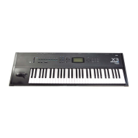
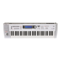
| Type | Workstation |
| Keyboard | 61 keys |
| Sequencer | 16-track |
| Display | LCD |
| Outputs | Stereo |
| Memory | Internal |