3
ELECTRICAL CONNECTIONS
24
OPTISONIC 3400
www.krohne.com 02/2015 - QS OPTISONIC 3400 - 4002741204-R04 en
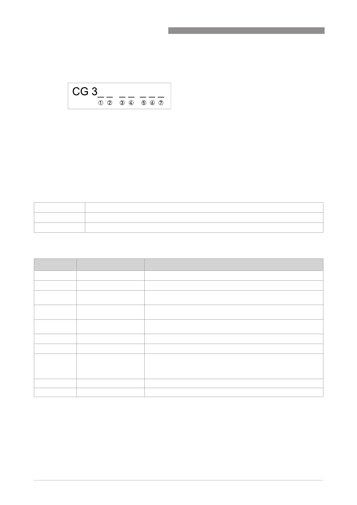
3.5.2 Description of the CG number
The last 3 digits of the CG number (5, 6 and 7) indicate the assignment of the terminal
connections. Please refer to the following examples.
Examples for CG number
Description of abbreviations and CG identifier for possible optional modules
on terminals A and B
Figure 3-6: Marking (CG number) of the electronics module and input/output variants
1 ID number:5
2 ID number: 0 = standard
3 Power supply option
4 Display (language versions)
5 Input/output version (I/O)
6 1st optional module for connection terminal A
7 2nd optional module for connection terminal B
CG 350 x1 100 100...230 VAC & standard display; basic I/O: I
a
or I
p
& S
p
/C
p
& S
p
& P
p
/S
p
CG 350 x1 7FK 100...230 VAC & standard display; modular I/O: I
a
& P
N
/S
N
and optional module P
N
/S
N
& C
N
CG 350 x1 4EB 24 VDC & standard display; modular I/O: I
a
& P
a
/S
a
and optional module P
p
/S
p
& I
p
Abbreviation Identifier for CG No. Description
I
a
A Active current output
I
p
B Passive current output
P
a
/ S
a
C Active pulse output, frequency output, status output or limit switch
(changeable)
P
p
/ S
p
E Passive pulse output, frequency output, status output or limit switch
(changeable)
P
N
/ S
N
F Passive pulse output, frequency output, status output or limit switch acc.
to NAMUR (changeable)
C
a
G Active control input
C
p
K Passive control input
C
N
H Active control input to NAMUR
Signal converter monitors cable breaks and short circuits acc. to
EN 60947-5-6. Errors indicated on LC display. Error messages possible
via status output.
- 8 No additional module installed
- 0 No further module possible