3
ELECTRICAL CONNECTIONS
22
OPTISONIC 3400
www.krohne.com 02/2015 - QS OPTISONIC 3400 - 4002741204-R04 en
100...230 VAC (tolerance range: -15% / +10%)
• Note the power supply voltage and frequency (50...60 Hz) on the nameplate.
• The protective ground terminal PE
PEPE
PE of the power supply must be connected to the separate U-
clamp terminal in the terminal compartment of the signal converter
24 VDC (tolerance range: -55% / +30%)
24 VAC/DC (tolerance ranges: AC: -15% / +10%; DC: -25% / +30%)
• Note the data on the nameplate!
• For measurement process reasons, a functional ground FE
FEFE
FE must be connected to the
separate U-clamp terminal in the terminal compartment of the signal converter.
• When connecting to functional extra-low voltages, provide a facility for protective separation
(PELV) (acc. to VDE 0100 / VDE 0106 and/or IEC 364 / IEC 536 or relevant national
regulations).
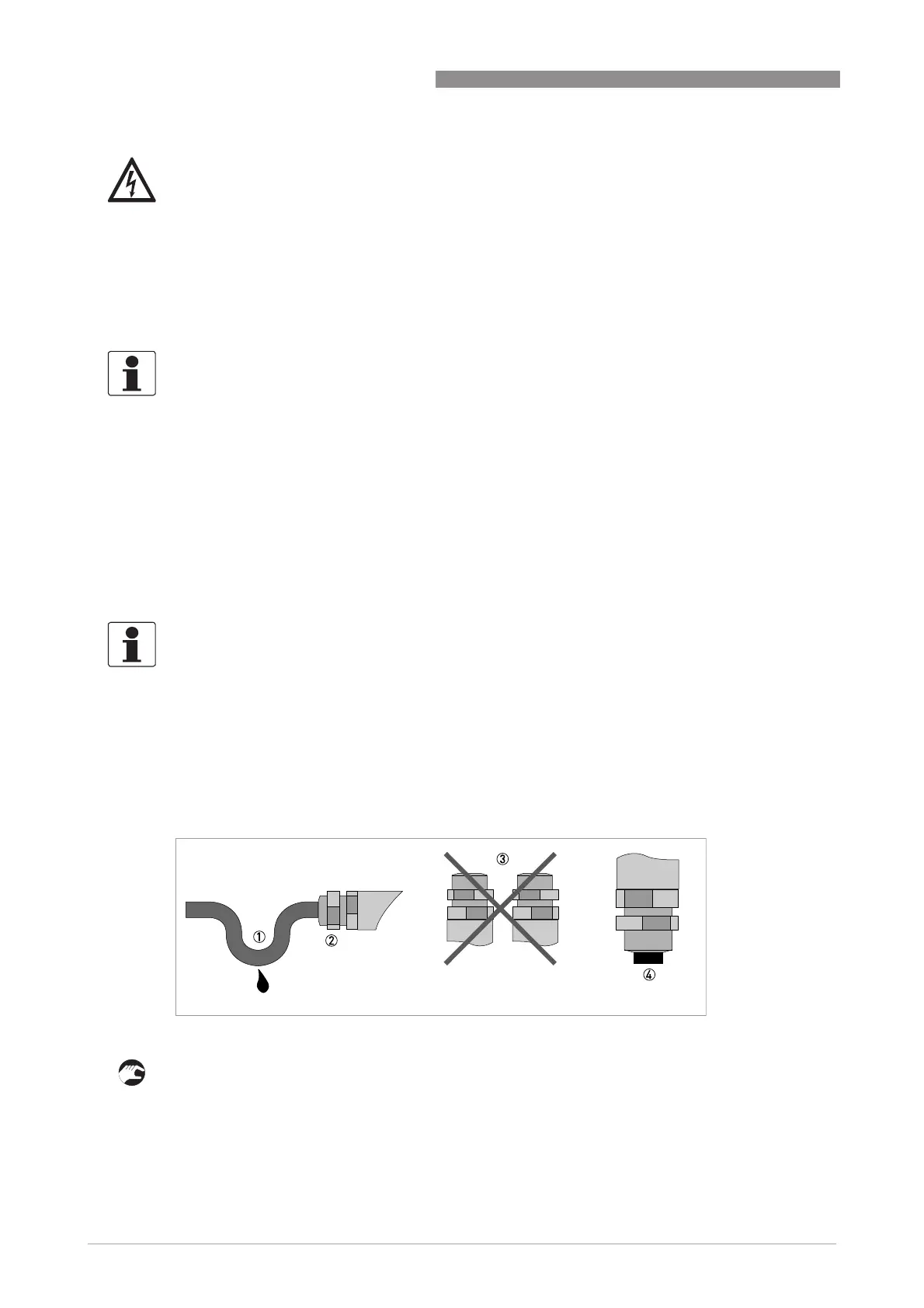
3.4 Laying electrical cables correctly
1 Lay the cable in a loop just before the housing.
2 Tighten the screw connection of the cable entry securely.
3 Never mount the housing with the cable entries facing upwards.
4 Seal cable entries that are not needed with a plug.
DANGER!
The device must be grounded in accordance with regulations in order to protect personnel
against electric shocks.
INFORMATION!
240 VAC+5% is included in the tolerance range.
INFORMATION!
For 24 VDC, 12 VDC-10% is included in the tolerance range.
Figure 3-5: Protect housing from dust and water