INSTALLATION
2
9
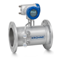
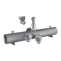
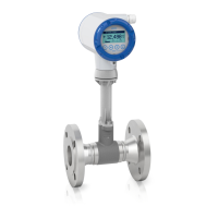
OPTISONIC 3400
www.krohne.com02/2015 - QS OPTISONIC 3400 - 4002741204-R04 en
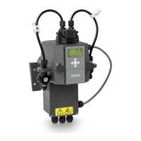
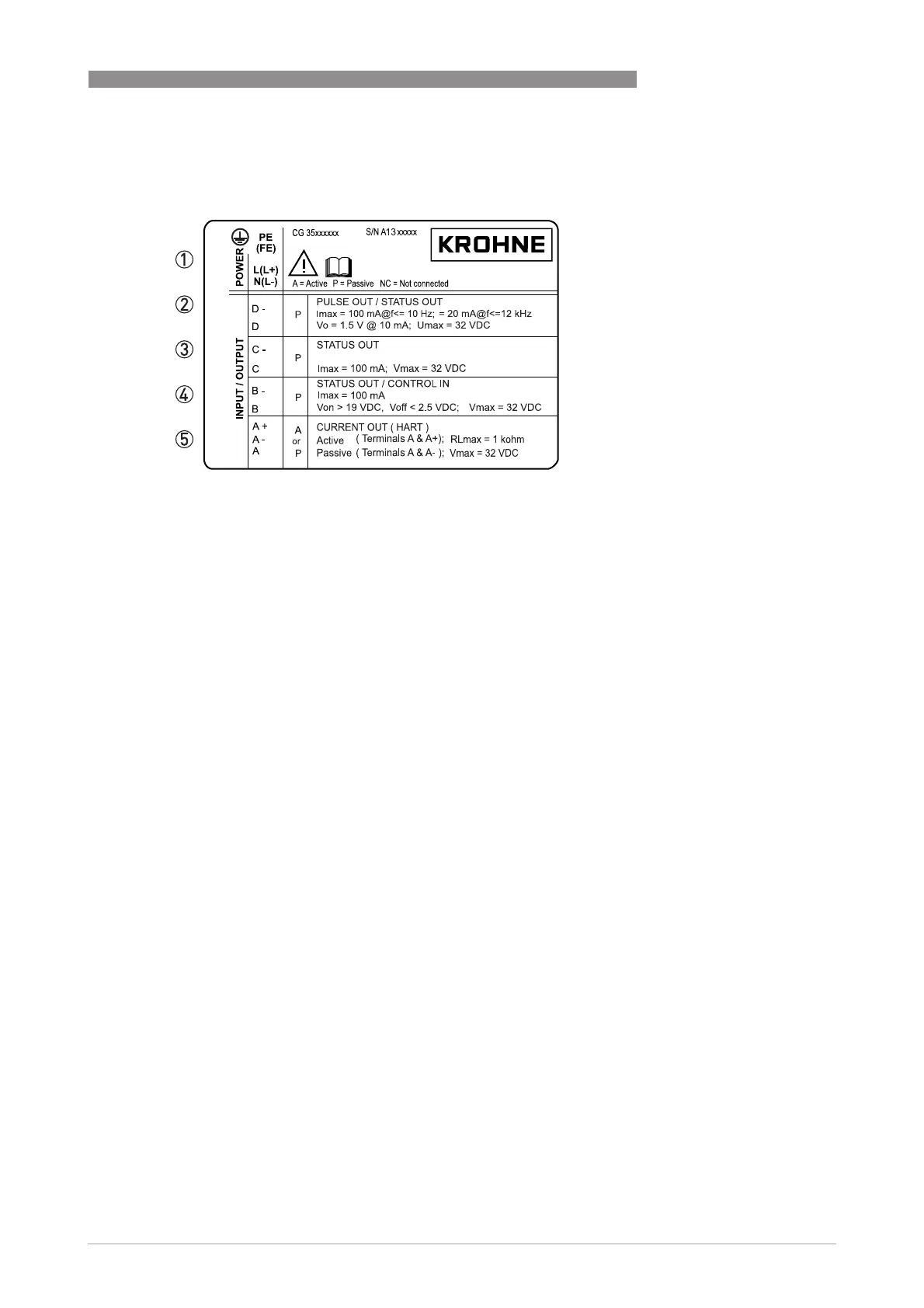
Electrical connection data of inputs/outputs (example of basic version)
Electrical connection data of inputs/outputs (example of basic version)Electrical connection data of inputs/outputs (example of basic version)
Electrical connection data of inputs/outputs (example of basic version)
• A = active mode; the signal converter supplies the power for connection of the subsequent
devices
• P = passive mode; external power supply required for operation of the subsequent devices
• N/C = connection terminals not connected
1 Power supply (AC: L and N, DC: L+ and L-, PE for ≥ 24V AC, FE for ≤ 24 VAC and DC)
2 Connection data of connection terminal D/D-
3 Connection data of connection terminal C/C-
4 Connection data of connection terminal B/B-
5 Connection data of connection terminal A/A-, A+ only operable in basic version