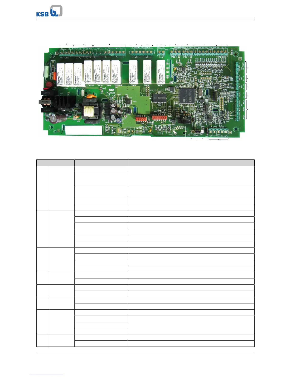
Fig.2: Mainboard
Table9: Connections on the mainboard
Terminal strip Terminal Description
1
J201
Power supply
L1 Power supply
Phase 1
L1 Power supply
Phase 1
N Power supply, neutral
PE PE power supply - earth
2 J601 Pump contactors and inlet tank valve
COM Pump contactors - earth
P1 Contactor of pump1
P2 Contactor of pump2
P3 Contactor of pump3
VALVE Inlet tank valve
3 J602 Activation of frequency inverters
F01 Start, frequency inverter 1
F02 Start, frequency inverter 2
F03 Start, frequency inverter 3
4 J605 B Output of alerts
URGENT Output for alerts
5 J605 A Output of warnings
NON URGENT Output for warnings
6 J604 Activation of frequency inverter
F0 START Start, floating frequency inverter
7 J404 Actual-value signal of pressure on discharge side
PT dis 24 V Pressure sensor, discharge side
PT dis +
PT dis -
8 J405 Actual-value signal of pressure on suction side
PT inl 24 V Pressure sensor, suction side