5 Installation at Site
19 of 88
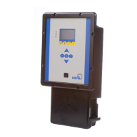
BoosterControl Advanced
Floating frequency inverter
Only possible when the frequency inverter is integrated in the control cabinet.
1. Observe the logic diagram (see other applicable documents).
2. Connect frequency inverter start signal:
Terminal strip J604, terminal FO START
Fixed frequency inverter
1. Connect frequency inverter start signal to the frequency inverter of the pump to
be controlled:
- Terminal strip J604, terminal FO START, frequency inverter per pump
CAUTION
Use of different types of frequency inverter
Damage to property!
▷ Only use frequency inverters of the same type within a system!
1. Connect frequency inverter start signal:
- Terminal strip J602, terminals F01 - F03
2. For 6 pumps also use the following additional terminals:
- Terminal strip J104, terminals F04 - F06
5.4.8 Making optional connections
Some terminals must be bridged if not in use.
Bridge the following terminals if not in use:
▪ Fault reporting relay of frequency inverter: terminal strip J403, terminal TFR with
COM
▪ Fault reporting relay of valve: terminal strip J403, terminal TVA with COM
▪ External Off switch: terminal strip J403, terminal OFF with COM
▪ Fire alert: terminal strip J403, terminal FIRE with COM
The following connections can be made.
External signalling devices
The external signalling device can be powered via the BoosterControl Advanced
control unit if necessary.
1. Bridge the following connections to power the external signalling device:
Terminal strip J201, terminal L1, with terminal strip J605A or J605B, left pin
2. Connecting external signalling devices:
- For warnings, terminal strip J605A, NON URGENT terminal
- For alerts, terminal strip J605B, URGENT terminal
Water flow detection (WSD)
Up to 3water flow detectors can be connected.
1. Connect existing water flow detector:
- Terminal strip J401, terminals WS1, WS2 and WS3
2. Connect a PT1000 temperature sensor, if any:
- Terminal strip J401, terminals PT1000 - and PT1000 +
Additional information on function and configuration