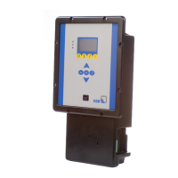
Fig.4: Control panel
Table11: Description of control panel
Item Description Function
1 Graphical display Displays information on BoosterControl Advanced
operation
2 "Traffic light" LEDs The traffic light function provides information
about the pump system's operating status.
3 Menu keys Change to the elements of the first menu level
4 Navigation keys Navigation and parameter setting
5 Service interface Configuring and parameterising BoosterControl
Advanced using a PC/notebook
6.1.1 "Traffic light" LEDs
The "traffic light" LEDs provide information about the operating status of
BoosterControl Advanced.
Table12: LED description
LED Description
Red
One or several alerts are active
Amber
One or several warnings are active
Green
Steady light: trouble-free operation
6.1.2 Graphical display
The graphical display breaks down into 6areas.