8 Commissioning/Start-up/Shutdown
35 of 88
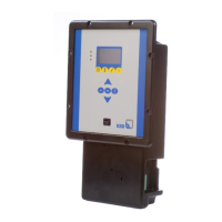
BoosterControl Advanced
Table28: Operating modes for pressure booster systems
Operating mode Description Section
Cascade control BoosterControl Advanced starts and stops additional
pumps as a function of pressure. (ðSection8.4.1,Page36
)
Cascade control with base load/
peak-load pump (jockey
operation)
In the operating mode with jockey pump, the jockey
pump is operated as a base-load pump at first. If
insufficient pressure is built up, one or more peak-
load pumps are added in cascading fashion. The
jockey pumps are switched off as the larger pumps
are cut in.
(ðSection8.4.2,Page37
)
Control with a floating frequency
inverter
BoosterControl Advanced controls one of the pumps
via a frequency inverter as a function of pressure.
Further pumps are started and stopped directly via
the mains. Before every system start-up, the control
system defines the pump with the least operating
hours as the pump to be controlled by the frequency
inverter.
If the frequency inverter fails, BoosterControl
Advanced switches to cascade control or switches off
the system.
(ðSection8.4.3,Page38
)
Control with one frequency
inverter per pump (sequential)
(VP)
BoosterControl Advanced controls all pumps via
frequency inverters as a function of pressure. After
the first frequency inverter-controlled pump has
reached its maximum output and a start time has
lapsed, the next frequency inverter-controlled pump
is cut in (pump with the fewest operating hours).
Deactivation also occurs sequentially.
(ðSection8.4.4,Page41
)
Control with one frequency
inverter per pump
BoosterControl Advanced controls all pumps via
frequency inverters as a function of pressure.
After the first frequency inverter-controlled pump
has been started and has reached its maximum
output, the next pump is cut in, and the pump
already running is simultaneously reduced in output
by xpercent (configurable) to avoid pressure surges.
The output of the second pump approaches that of
the first until both generate the same output, etc.
Then both pumps run synchronously at the same
speed in parallel operation until the output limit is
reached and the next pump is cut in or out. During
the switching procedure, the remaining pumps are
adapted in their output.
(ðSection8.4.5,Page42
)