9 Related Documents
63 of 76
CTN / CTN-H
902.09
920.09
550.02
452.02
454.02
411.47
461.02
451.02
904.14
412.32
K/H
458.02
524.02
562.06
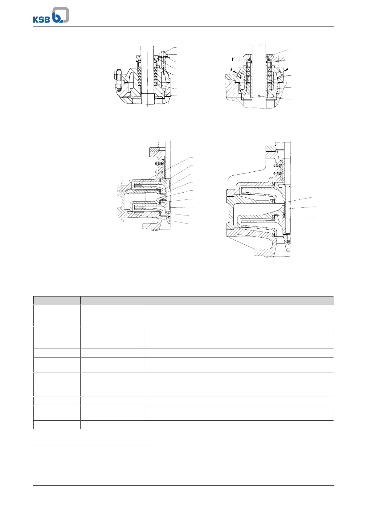
Standard design, without shaft protecting
sleeve
Design with shaft protecting sleeve and
lantern ring in the gland packing; can be
cooled/heated
901.28
(902.28)
920.28
901.27
(902.27)
920.27
411.57
230.01
525
108
940.03
230.02
411.58
502.03/561.07
502.04/561.08
Detail of two-stage pump
Sizes: 25-200/2 and 40-250/2
Additional lock for PTFE bearings
Detail of two-stage pump
Sizes: 40-280/2, 50-315/2, 80-315/2,
100-315/2, 125-315/2
Table31: List of components
Part No. Description Scope of supply
102 Volute casing with gasket 400.16, casing wear ring 502.02
27)
, grooved pin 561.06
27)
,
grub screw 904.04
28)27)
/.10, hexagon head bolt 901.28
27)
, stud 902.28
27)
,
hexagon nut 920.10/.28
108 Stage casing
29)
with joint ring 411.58, casing wear ring 502.03/.04, grub screw
904.07
27)28)
/.08
27)28)
, bearing bush 545.02
27)
, grooved pin 561.09
27)
, hexagon
head bolt 901.27
27)
, stud 902.27
27)
, hexagon nut 920.27
153 Suction nozzle
27)
with gasket 400.03, hexagon head bolt 901.26, hexagon nut 920.26
162 Suction cover with joint ring 411.57, casing wear ring 502.01
27)
, grooved pin
561.01
27)28)
, grub screw 904.03
27)28)
210 Shaft
30)28)
with set of spacer discs 550.21, keywayed nut 920.21, cap nut 920.22,
parallel pin 562.06
27)
, lockwasher 931.01/.02, key 940.01/.02/.03
29)
211 Pump shaft with cap nut 920.22, lockwasher 931.02, key 930.01/.03
29)
212 Intermediate shaft
28)
213 Drive shaft with set of spacer discs 550.21, parallel pin 562.06
27)
, with keywayed nut
920.21, lockwasher 931.01, key 940.02
230.01/.02 Impeller For two-stage pumps, specify whether for 1st or 2nd stage
27) If fitted
28) Not shown
29) Only for two-stage pumps
30) If only one shaft is fitted: For large installation depths, the shaft assembly consists of a pump shaft and drive shaft or pump
shaft, intermediate shaft(s) and drive shaft