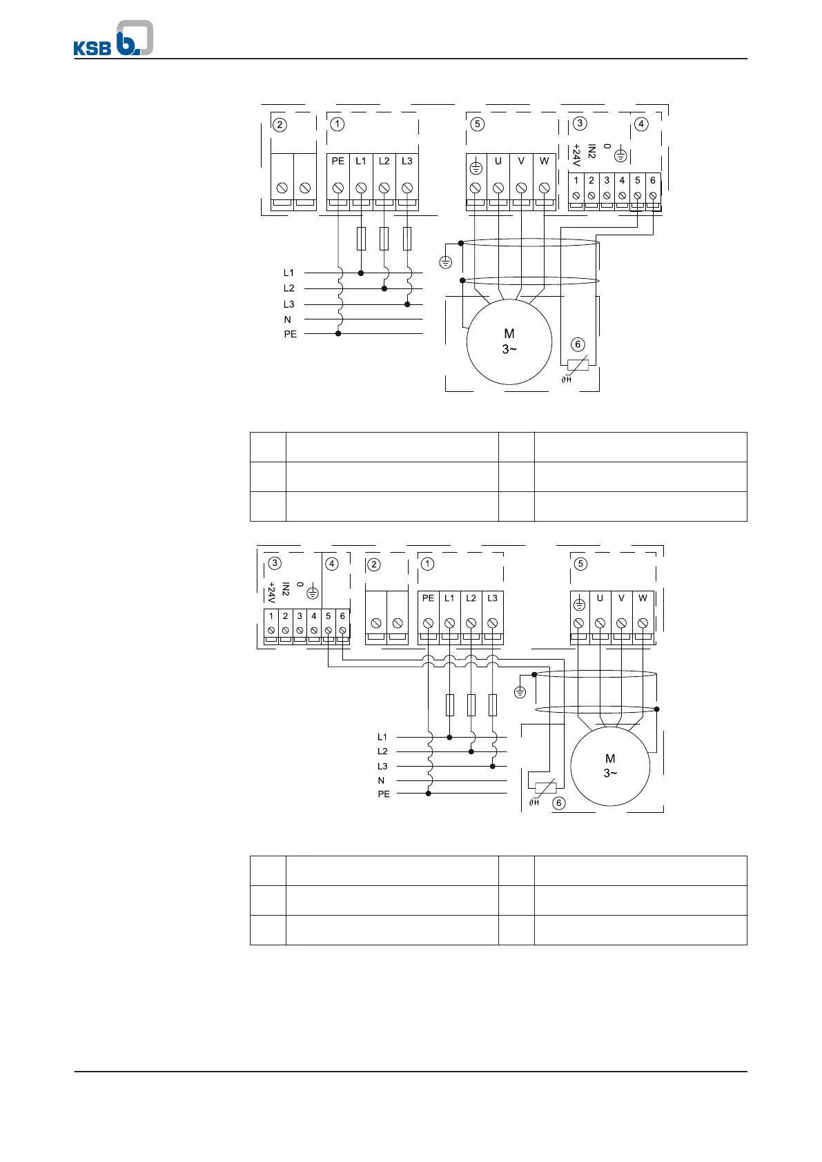
Fig. 10: Establishing the power supply and motor connections, size C
① Mains connection (P2 terminal
block)
② Braking resistor (P3 terminal block)
③ Sensor connection (P5 terminal
block)
④ PTC connection (P5 terminal block)
⑤ Motor connection (P4 terminal
block)
⑥ Motor PTC
Fig. 11: Establishing the power supply and motor connections, size D
① Mains connection (P2 terminal
block)
② Braking resistor (P3 terminal block)
③ Sensor connection (P5 terminal
block)
④ PTC connection (P5 terminal block)
⑤ Motor connection (P4 terminal
block)
⑥ Motor PTC
Connect the cores for a PTC connection/PTC thermistor to terminal strips 5/6. If no
PTC connection is available on the motor end, parameter 3-3-5-1 must be
deactivated.
Terminal 1-4: Alternative connection of an analog input AIN2 (⇨ Section 5.4.3.6 Page
31)
Size C
Size D
Connect motor monitoring
(PTC/PTC thermistor)
Connecting the sensors
5 Installation at Site
28 of 162
PumpDrive