bar is used, this range corresponds to an actual value signal range of 0 - 100 %. If the
required setpoint is, for example, 4.5 bar, a setpoint of 75 % would have to be
specified. The unit of setpoint and actual value is defaulted to [%].
Table 48: Parameters for unit of setpoint and actual value
Parameter Description Possible settings Factory setting
3-2-2-1
Physical unit of setpoint Selection list III (⇨ Section 10.1
Page 129)
1
3-2-2-2
Physical unit of flow rate (Q) 29
3-2-2-3
Physical unit of pressure 1
3-5-1-3
Maximum setpoint For unit %: Select 100 %
For units bar, m, m
3
/h,...: Set to
full-scale value of the sensor,
e.g. 6 bar
100
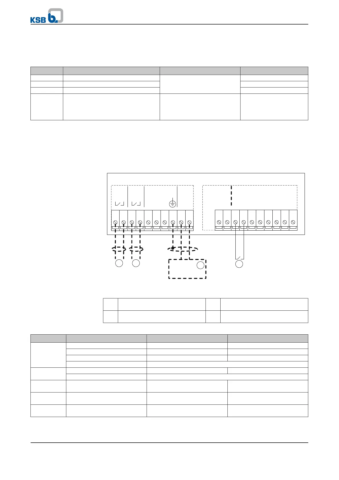
7.1.1.3 Open-loop control mode
In open-loop control mode, PumpDrive translates the specified setpoint into the
corresponding motor speed. The process controller is deactivated. PumpDrive starts
up in automatic mode if digital input 1 is supplied with +24 V DC (terminal strip
P4:13/14). Circuit diagram (⇨ Section 9 Page 99)
GN
D
DI6
DI5
DI4
DI3
DI2
DI1
+24V
AGND
AN-OUT
20191817161514131211
1
AGND
AIN1
GND
AIN2
+24
V
NO2
CO
M2
NO1
COM1
10931 2 4 5 6 7 8
P4
P7
2
0V
S ignal
3 4
Fig. 25: Terminal wiring diagram, open-loop control mode (dashed line = optional)
1 Start/stop 2 External setpoint signal
(⇨ Section 7.1.1.2 Page 49)
3 Signal relay 1
(⇨ Section 7.4.2 Page 95)
4 Signal relay 2
(⇨ Section 7.4.2 Page 95)
Table 49: Open-loop control mode
Function Input/connection Specification Setting range/parameter value
Setpoint
specification
P7 terminal strip Analog input 1 (P7: 9/10) 5-10 V DC ≙ 25-50 Hz
Graphical control panel Configurable setpoint
(3-5-2-1)
50 - 100 % ≙ 25 - 50 Hz
Standard control panel (⇨ Section 6.1.5 Page 39) 50 - 100 % ≙ 25 - 50 Hz
Field bus See field bus module literature
Start
command
P4 terminal strip Digital input 1 (P4: 13/14) Start in automatic mode
Field bus See field bus module literature
Process
controller
Graphical control panel PI Auto (3-9-1-6) Deactivated
Process
controller
Graphical control panel PI mode (3-9-1-1) Disabled
Operating
mode
Graphical control panel MAN-OFF-AUTO AUTO
7 Commissioning/shutdown
PumpDrive
51 of 162