3-12-3-7
Q0
3-12-3-8
Q1
3-12-3-9
Q2
3-12-3-10
Q3
3-12-3-11
Q4
3-12-3-12
Q5
3-12-3-13
Q6
3-12-3-4
Qopt
3-12-3-6
Qmax
3-12-3-5
Qmin
2
1
1
0
105
2
15 20 25 30
[kW]
P0
P1
P2
P3
P4
P5
P6
3-12-3-14
H0
3-12-3-15
H1
3-12-3-16
H2
3-12-3-17
H3
3-12-3-18
H4
3-12-3-19
H5
3-12-3-20
H6
3
3-12-3-21
P0
3-12-3-22
P1
3-12-3-23
P2
3-12-3-24
P3
3-12-3-25
P4
3-12-3-26
P5
3-12-3-27
P6
4
10
0
105
15
15
20
20
25
25 30
[m]
Q0
Qmin Q1 Q2 Q3
Q4
Qopt Q5 Q6Qmax
H1
H2
H3
H4
H5
H6
H0
Qmin
Qmax
169.0
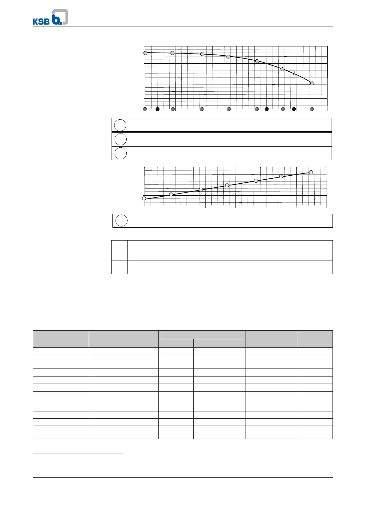
Fig. 43: Characteristic curve entry
1 Parameterisation of Qmin, Qopt, and Qmax for the respective pump
2 Parameterisation of 7 equidistant flow rate points Q0, Q1, ... Q6
3 Parameterisation of the 7 head points H0, H1, ... H6 for Q0, Q1, ... Q6
4 Parameterisation of the 7 power requirement points P0, P1, ... P6 for Q0,
Q1, ... Q6
The following parameters have to be set to match PumpDrive to the driven pump.
Refer to the pump product literature for the values to be set.
When using multistage pumps, make sure that the power data set using parameters
3-12-3-21
to
3-12-3-27
corresponds to the total pump input power. It may be required
to adjust parameters to account for the number of stages, starting with the
characteristic curve as a basis.
Table 74: Parameters for matching PumpDrive to the pump
Parameter Description Possible settings Unit Factory
setting
33)
Min. Max.
3-12-3-1
Pump nominal speed 0 9999 rpm 0
3-12-3-2
Rho 10 0 9999 kg/mm
3
1000
3-12-3-3
No of stages 0 100
1
3-12-3-4
Q
opt
0 9999 m
3
/h 0
3-12-3-5
Q
min
0 9999 m
3
/h 0
3-12-3-6
Q
max
0 9999 m
3
/h 0
3-12-3-7
Q_0 0 9999 m
3
/h 0
3-12-3-8
Q_1 0 9999 m
3
/h 0
3-12-3-9
Q_2 0 9999 m
3
/h 0
3-12-3-10
Q_3 0 9999 m
3
/h 0
3-12-3-11
Q_4 0 9999 m
3
/h 0
3-12-3-12
Q_5 0 9999 m
3
/h 0
3-12-3-13
Q_6 0 9999 m
3
/h 0
Multistage pumps
33)
Pump-specific values are preset during factory parameterisation.
7 Commissioning/shutdown
PumpDrive
77 of 162