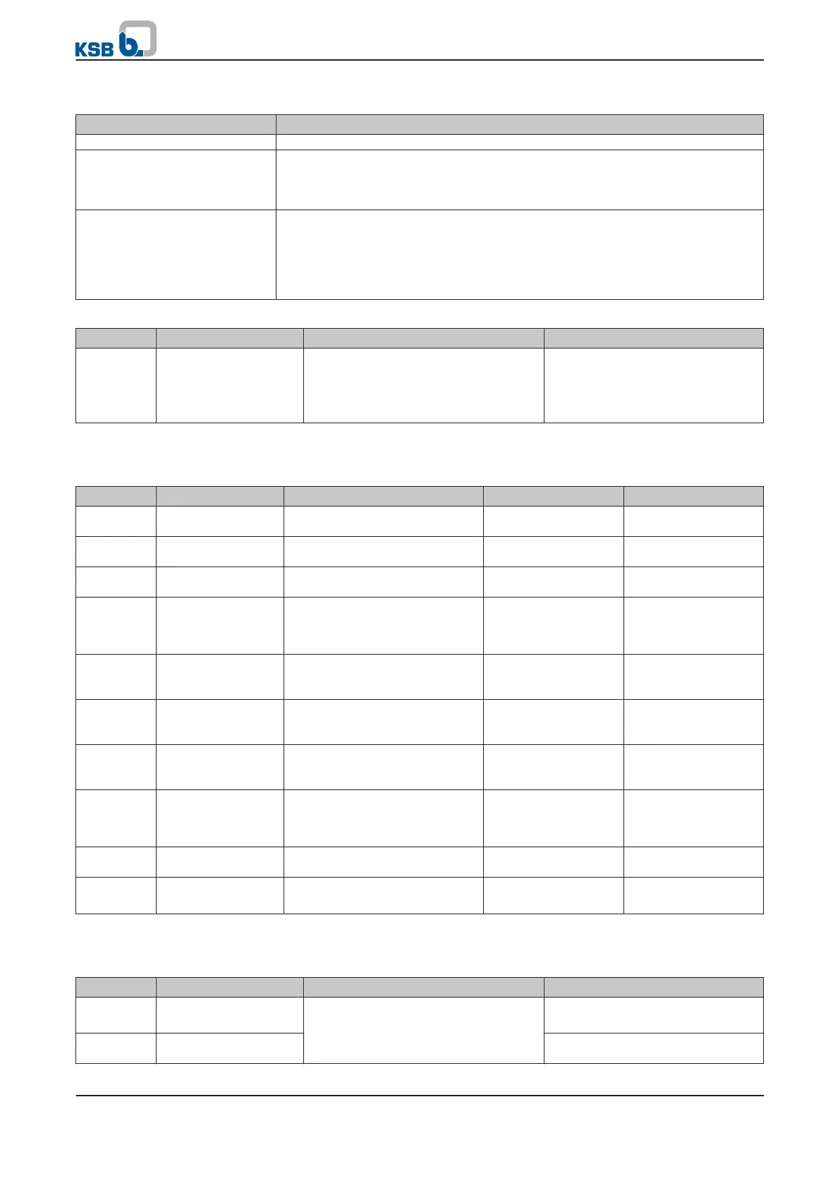
Table 80: Selection options for the response to limit value violation
Selection option Description
No Function Limit value monitoring is deactivated.
Warning When a limit value is violated, the amber LED lights up and the associated
message flashes on the display. The information about a current limit value
violation can also be provided via a digital output (
3-7-2-1
or
3-7-3-1
(⇨ Section
7.4 Page 94)
Stop & Trip When a limit value is violated, the speed is reduced along the ramp function
until the unit comes to a stop. The red LED lights up and the associated message
flashes on the display. The restart behaviour depends on the trip reset mode (
3-11-2-1
). The information about a current limit value violation can also be
provided via a digital output (parameter
3-7-2-1
or
3-7-3-1
(⇨ Section 7.4 Page
94)
Table 81: Parameters for restart behaviour after limit value violation
Parameter Description Possible settings Factory setting
3-11-2-1
Trip Rest Mode 1 - Manual Reset
2 - 10 s, 60 s, 5 min.
3 - Reset every 5 min
4 - 10 s, 60 s, 5 min., 1 h
5 - Reset every 15 min
2 - 10 s, 60 s, 5 min.
Monitoring of the motor current and output frequency
Table 82: Parameters for monitoring the motor current and output frequency
Parameter Description Possible settings Reference to Factory setting
3-6-2-1
Current monitoring
lower limit
0..100 (%)
3-11-4-2
0 %
3-6-2-2
Current monitoring
upper limit
0..100 (%)
3-11-4-2
100 %
3-6-2-3
Current monitoring
time delay
0..60 (s) - 5 s
3-6-2-4
Current monitoring
function
1 - No Function
2 - Warning
3 - Stop and Trip
- 1 - No Function
3-6-2-5
Frequency
monitoring lower
limit
0..100 (%)
3-11-4-1
0 %
3-6-2-6
Frequency
monitoring upper
limit
0..100 (%)
3-11-4-1
100 %
3-6-2-7
Frequency
monitoring time
delay
0..60 (s) - 5 s
3-6-2-8
Output frequency
warning function
1 - No Function
2 - Warning
3 - Stop and Trip
- 1 - No Function
3-11-4-1
Maximum output
frequency
1..600 (Hz) - 50 Hz
3-11-4-2
Maximum output
current
0..500 (A)
Access: Factory
- Depending on the size
Monitoring analog inputs 1 and 2
Table 83: Parameters for monitoring analog inputs 1 and 2
Parameter Description Possible settings Factory setting
3-6-3-1
Lower limit
Analog input 1
Analog IN 1 Low
(3-8-2-7)
to Analog IN
1 High
(3-8-2-8)
in Analog IN 1 Unit
(3-8-2-6)
0
3-6-3-2
Upper limit for analog
input 1
100
7 Commissioning/shutdown
PumpDrive
83 of 162