S-70
07-E3B SERIES, WSM
ENGINE
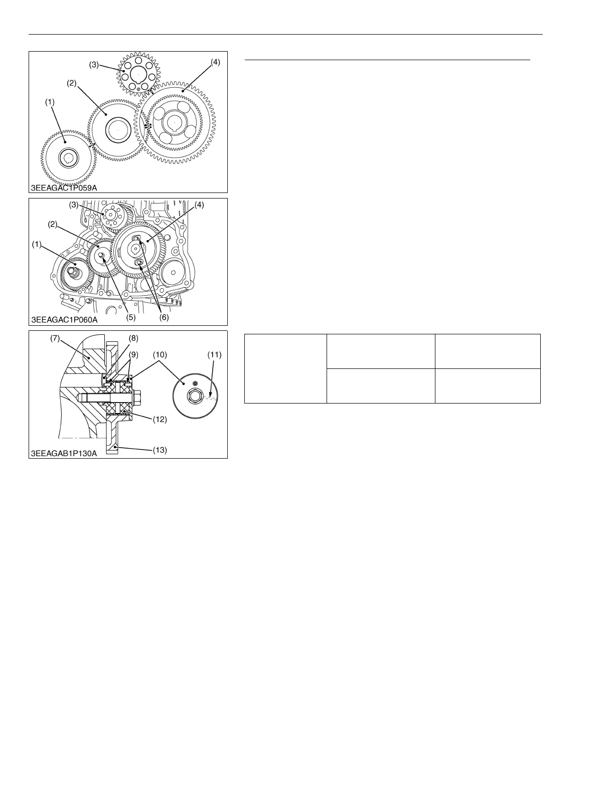
Camshaft and Idle Gear (for V2607-DI-E3B / V2607-DI-T-E3B)
1. Rotate the cylinder head side of the engine crankcase to the
lower side.
2. Remove the camshaft set screws (6) and draw out the cam gear
(4).
3. Remove the idle gear mounting screws (5) and draw out the idle
gear (2).
• If the cylinder head side of the engine crankcase does not
become lower side, the tappets drop and become the trouble
to the camshaft. The camshaft will not be able to be drawn
out.
(When reassembling)
• When installing the idle gear (2) and cam gear (4), be sure to
place the 4th cylinder piston at the top dead center in
compression then, align all mating marks on each gear to
assemble the timing gears, set the cam gear last.
• Mount the injection pump gear (1) after installing the flywheel
housing.
• Make sure the idle gear shaft (12) is clean.
• Apply oil to the idle gear shaft (12) and set the crankcase 1 (7).
• Set the idle gear (13) and the collar (10) with the oil groove (11)
facing crankcase 1 side.
W1294222
Tightening torque
Camshaft set screw
24 to 27 N·m
2.4 to 2.8 kgf·m
18 to 20 lbf·ft
Idle gear mounting screw
49 to 55 N·m
5.0 to 5.7 kgf·m
37 to 41 lbf·ft
(1) Injection Pump Gear
(2) Idle Gear
(3) Crank Gear
(4) Cam Gear
(5) Idle Gear Mounting Screw
(6) Camshaft Set Screw
(7) Crankcase 1
(8) Plug
(9) Spring Pin
(10) Collar
(11) Oil Groove
(12) Idle Gear Shaft
(13) Idle Gear
 Loading...