S-71
07-E3B SERIES, WSM
ENGINE
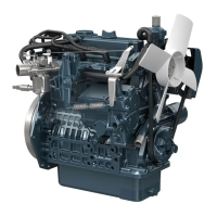
Camshaft and Idle Gear (for V3007-DI-T-E3B / V3307-DI-T-E3B)
1. Rotate the cylinder head side of the engine crankcase to the
lower side.
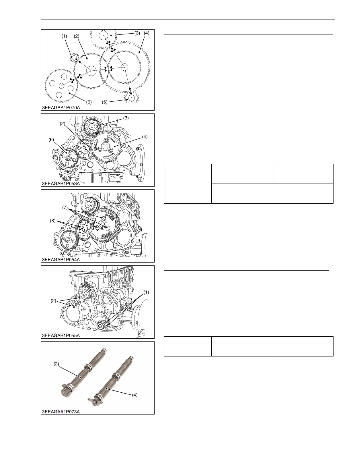
2. Remove the camshaft set screws (7) and draw out the cam gear
(4).
3. Remove the idle gear mounting screws (8) and draw out the idle
gear (2).
• If the cylinder head side of the engine crankcase does not
become lower side, the tappets drop and become the trouble
to the camshaft. The camshaft will not be able to be drawn
out.
(When reassembling)
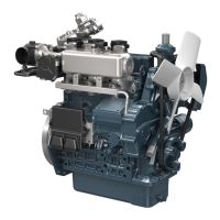
• When installing the idle gear (2) and cam gear (4), be sure to
place the 4th cylinder piston at the top dead center in
compression then, align all mating marks on each gear to
assemble the timing gears, set the cam gear last.
• Mount the injection pump gear (6) after installing the flywheel
housing.
W1189797
Balancer Shaft (Option for V3007-DI-T-E3B / V3307-DI-T-E3B)
1. Remove the balancer shaft 1 set screws (1) and draw out the
balancer shaft 1 (3).
2. Remove the balancer shaft 2 set screws (2) and draw out the
balancer shaft 2 (4).
(When reassembling)
• When installing the balancer shaft 1 (3) and 2 (4), be sure to
place the 4th cylinders piston at the top dead center in
compression then, align all mating marks on each gear to
assemble the timing gears, set the cam gear last.
W1191037
Tightening torque
Camshaft set screw
24 to 27 N·m
2.4 to 2.8 kgf·m
18 to 20 lbf·ft
Idle gear mounting screw
30 to 34 N·m
3.0 to 3.5 kgf·m
22 to 25 lbf·ft
(1) Balancer 2 Gear (Option)
(2) Idle Gear
(3) Crank Gear
(4) Cam Gear
(5) Balancer 1 Gear (Option)
(6) Injection Pump Gear
(7) Camshaft Set Screw
(8) Idle Gear Mounting Screw
Tightening torque Balancer shaft set screw
24 to 27 N·m
2.4 to 2.8 kgf·m
18 to 20 lbf·ft
(1) Balancer Shaft 1 Set Screw
(2) Balancer Shaft 2 Set Screw
(3) Balancer Shaft 1
(4) Balancer Shaft 2
 Loading...