InstallationInstalling in a Wired Network
2-3
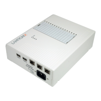
The following tables explains the function of the LEDs.
The PCC1 and PCC2 LEDs, which correspond to the top and bottom PC card slot respectively, vary in
meaning depending on what kind of card is currently installed.
Note: Although a red LED during boot mode usually signals an error, red LED patterns are
part of the normal operation of the MSS and are not necessarily indicative of errors or
dangerous operation.
Installing in a Wired Network
The MSS should be positioned close to the device it will be servicing. Since powering down the unit will
terminate any active sessions, it may be desirable to place the server in a location secure from user access.
Also be aware of the unit’s environmental operating limits and cabling requirements. See
Appendix C and
Appendix E for details.
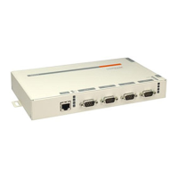
Table 2-1: MSS4 LEDs
LED Function
Serial (1-4) Blinks green to indicate MSS serial activity.
OK Blinks yellow, green, or red to indicate MSS activity.
Link Glows green or yellow to indicate a wired Ethernet connection.
Off: Not connected to a wired Ethernet network
Green: Connected to a 10BASE-T network
Yellow: Connected to either a 100BASE-T or 100BASE-FX network
Table 2-2: PCC1 and PCC2 LEDs
LED State 802.11 Cards ATA Cards Modem cards
Off No card inserted No card inserted No card inserted
Green Solid 802.11 link established,
PC card ready for use
PC card ready for use PC card ready for use
Green Blinking Negotiating settings with
AP or ad-hoc peer
PC card is not properly
formatted
n/a
Red Solid PC card hardware failure PC card hardware failure PC card hardware failure
Red Blinking PC card not read or
supported
PC card not read or
supported
PC card not read or
supported
Yellow Solid PC card identified,
initialization in progress
PC card identified,
initialization in progress
PC card identified,
initialization in progress
Yellow Blinking Scanning for Access Point
(AP) or ad-hoc peer
n/a Card identified,
initialization problem
 Loading...
