Installation Installing PC Cards
2-6
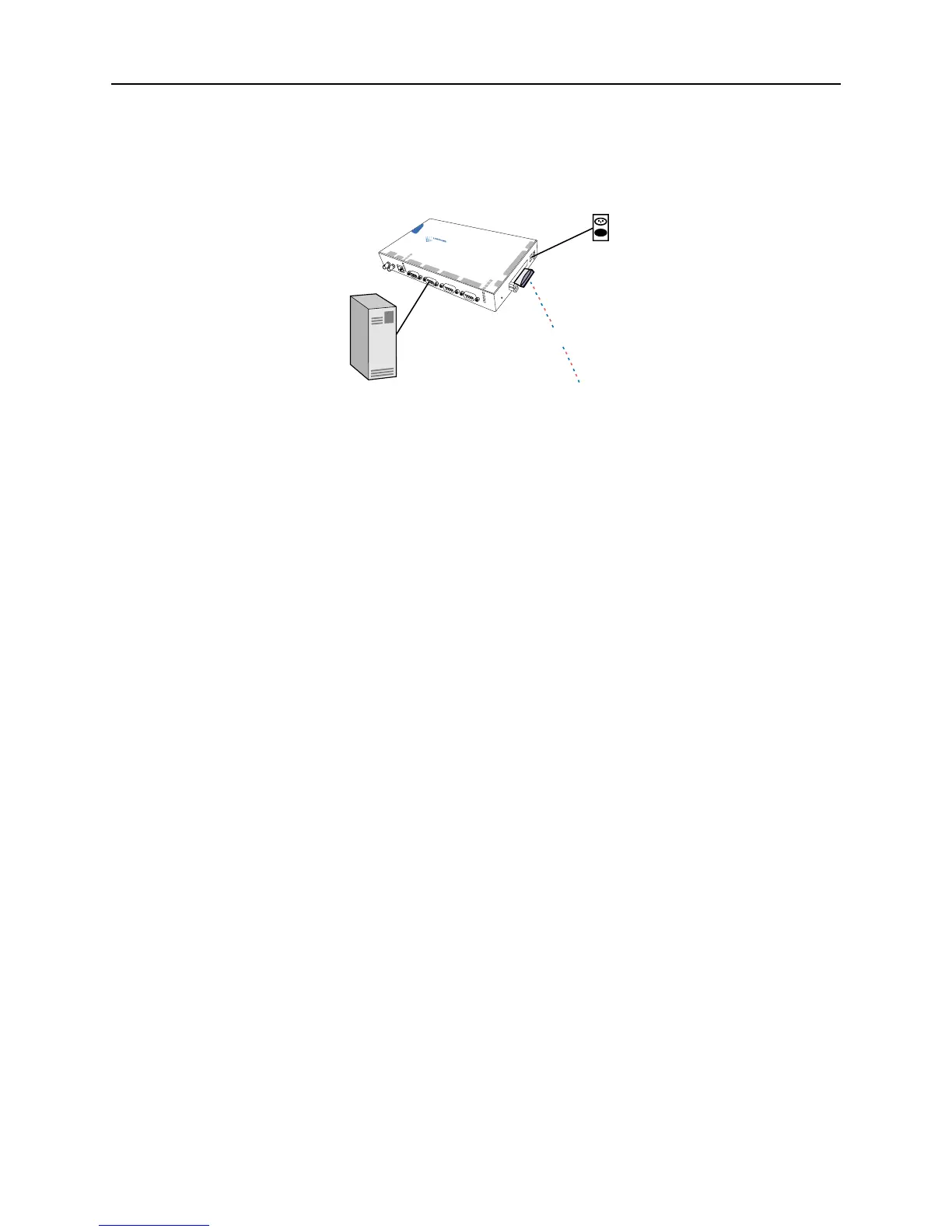
The following diagram shows a properly-installed MSS in a wireless Ethernet network. Be sure to read your
PC card manual for specific placement and distance requirements.
Figure 2-6: MSS Connected to Serial Device and Wireless Network
Follow these steps to properly install an 802.11 card.
1 Power off the MSS by removing the plug from the outlet.
2 Insert a supported 802.11 card into one of the PC card slots.
3 Power up the MSS by plugging the power supply back in the outlet.
The MSS should begin its normal boot process. Once the process is complete, one of the PC Card
LEDs should remain lit as long as there is an 802.11 card inserted in the corresponding PC card slot.
When the PC card LED corresponding to the installed card is solid green, the MSS is ready for
use.
If your PC card LED is any other color, refer to Table 2-1 on page 2-3 for information on what that
color means.
Installing an ATA Flash Card
Follow these steps to properly install supported ATA flash and disk storage cards.
1 Power off the MSS by unplugging its power cable.
2 Insert a supported ATA Flash card into one of the PC card slots.
3 If desired, insert another supported ATA Flash card into the other PC card slot.
4 Power up the MSS by plugging its power cable into the outlet.
The MSS should boot up normally.
If a PC card LED is a solid green, the ATA card in the corresponding slot is ready for use.
If a PC card LED blinks green, the ATA card in the corresponding slot must be formatted before
it can be used. Proceed to Formatting an ATA Flash Card on page 4-17 for details.
If a PC card LED is any other color, refer to Table 2-1 on page 2-3 for information on what that
color means.
M
S
S
4
s
e
r
i
a
l
4
s
e
r
ia
l
3
s
e
r
i
a
l
2
s
e
r
i
a
l
1
pc ca
rd 1
p
c
ca
r
d 2
li
n
k
ok
10
/
100
10
0
Ba
s
e
F
X
TX
RX
se
r
ia
l
1
2
3
4
reset
pc card
1
2
9
-
30vdc
Device
Serial
Wireless
(to network)
MSS4

 Loading...