LT-3100 User & Installation Manual Rev. 1.06 Interfaces
Lars Thrane A/S www.thrane.eu Page 27 of 155
Interfaces
LT-3110 Control Unit
This section will describe all the external interfaces from the LT-3110 Control Unit.
DC input (PWR)
The LT-3100 system is designed to be used on 12 VDC and 24 VDC power buses (nominal). External DC
power to the LT-3100 system is provided by connecting the proprietary 91-102118 Power Cable, 3m -
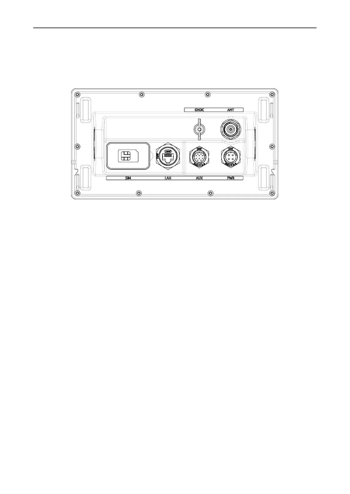
delivered by Lars Thrane A/S. The power connector is mounted on the back side of the LT-3110 Control Unit
and marked ‘PWR’, see Figure 31.
The power source for the LT-3100 system must comply with the regulations and the associated standards,
minimum is compliance to IEC 60945 (2002). When extending the power supply cables the positive (+) and
the negative (-) must be installed closely together in order to keep the cable inductance low.
NOTE: Make sure to use a galvanic isolated power supply, see Galvanic Isolated Power Supply on
page 41.
NOTE: The input voltage range is: 12-24 VDC. The LT-3110 Control Unit DC input connector and
circuit is protected and certified for Reverse Polarity Protection.
NOTE: A power connector (4-pole) is used for the LT-3110 Control Unit. This power connector
requires the new 91-102118 power cable, 3m from Lars Thrane A/S. Use only the 91-
102118 power cable, 3m delivered by Lars Thrane A/S. If power connector (2-pole) is used
for the LT-3110 Control Unit, then use the 91-100767 power cable, 3m delivered by Lars
Thrane A/S.