April 8, 2011 HN FAQ Memo, Version 3.0 Page 31 of 108
3.1.7.5 BD3 installation, (Parlour only)
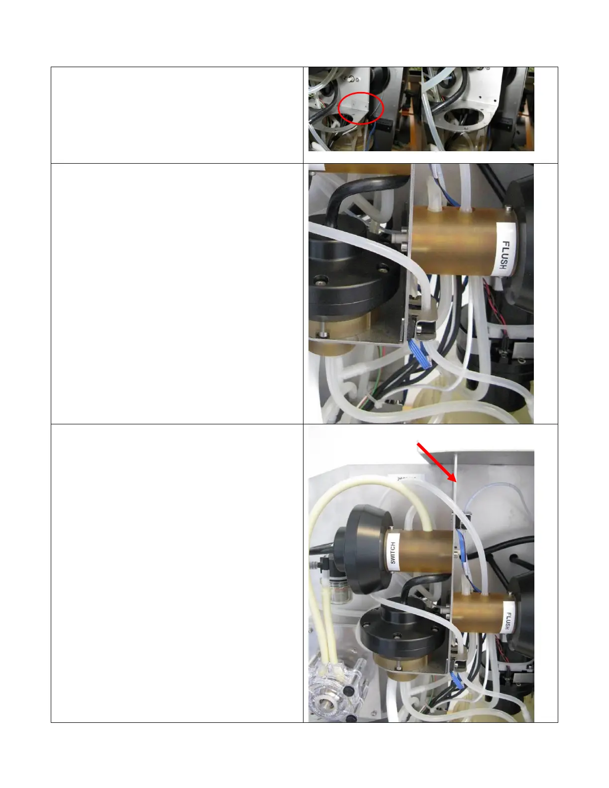
The sensor is to be fixed to the cabinet through
ø4mm holes which have to be drilled in the valve
bracket on the cabinet. Remove the SI filter unit
before drilling. Use the sensor bracket bottom
plate to mark up for the holes.
Mount the sensor as described in appendix 2
approximately 150mm from the ø3 (ID) tube end.
The ø3 (ID) tube end is connected to the MV
tube with pn:60045272 tube/tube connector.
As the valve bracket is between the sensor
bracket and the bottom plate the allen screws used
are 12mm long instead of the original 10mm.
(supplied with upgrade kit). The sensor cord
should go out from beneath the sensor to prevent
water running down the cord in the sensor.
The ø3 (ID) silicone tube should go from the
sensor around the switch valve and then connect
to the filter flush valve
Upgrade kit BOM:
1 x 700mm ø3 (ID) silicone tube pn:00702571
1 x tube/tube connector pn: 60045272
2 x M3x12 allen screws pn: 00219147