MIPI DSI to OpenLDI/FPD-Link/LVDS Interface Bridge Soft IP
User Guide
© 2016 Lattice Semiconductor Corp. All Lattice trademarks, registered trademarks, patents, and disclaimers are as listed at www.latticesemi.com/legal. All other brand or product names are
trademarks or registered trademarks of their respective holders. The specifications and information herein are subject to change without notice.
10 FPGA-IPUG-02003-1.2
VSYNC HSYNCDE VSYNC HSYNCDE
R0
G1
B2
R1
G2
B3
R2
G3
B4
R3
G4
B5
R4
G5
R5
B0
G0
B1
R0
G1
B2
R1
G2
B3
R2
G3
B4
R3
G4
B5
R4
G5
R5
B0
G0
B1
Current Cycle Next Cycle
RES RESR6R7G6G7B6B7 R6R7G6G7B6B7
clk_ch0_p_o
d0_ch0_p_o
d1_ch0_p_o
d2_ch0_p_o
d3_ch0_p_o
VSYNC HSYNCDE VSYNC HSYNCDE
R0
G1
B2
R1
G2
B3
R2
G3
B4
R3
G4
B5
R4
G5
R5
B0
G0
B1
R0
G1
B2
R1
G2
B3
R2
G3
B4
R3
G4
B5
R4
G5
R5
B0
G0
B1
RES RESR6R7G6G7B6B7 R6R7G6G7B6B7
clk_ch1_p_o
d0_ch1_p_o
d1_ch1_p_o
d2_ch1_p_o
d3_ch1_p_o
1st pixel received
2nd pixel received
3rd pixel received
4th pixel received
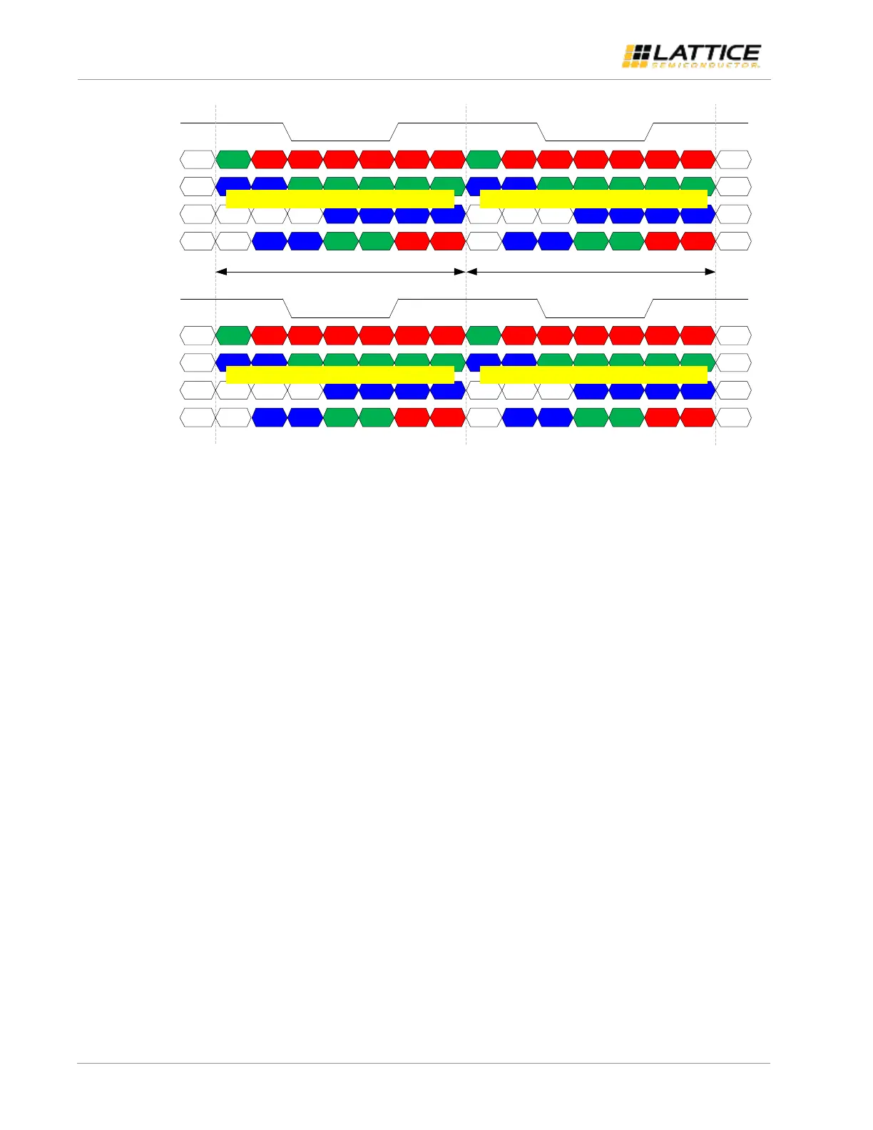
Figure 2.8. Single MIPI DSI to Dual FPD-Link (Split) Timing Diagram
Each data lane is serialized using ODDRx7 or ODDRx14 primitive, depending on Tx gear setting (TX_GEAR). RGB888
requires 4 data lanes while RGB666 requires 3 data lanes only. The clock lane is generated by feeding constant
“1100011” or “11000111100011” to another ODDRx7 or ODDRx14, respectively. The clock is edge-aligned against data.
Seven bits of data are transmitted in one clock cycle. When TX_GEAR is 14, the first pixel received is transmitted first
and the second pixel received is transmitted in the next clock cycle.
In single MIPI DSI to dual FPD-Link configuration, the incoming packets are split into the two channels in an alternate
manner. The first pixel received is transmitted over LVDS channel 0 while the next pixel received is transmitted over
LVDS channel 1 at the same clock cycle as shown in Figure 2.8. The same approach is implemented regardless of
TX_GEAR setting.
The dual MIPI DSI to dual FPD-Link configuration is two instances of single MIPI DSI to single FPD-Link that share the
same clocks. When MIPI D-PHY clock is continuous, the continuous byte clock from Rx channel 0 is used.
2.2. D-PHY Common Interface Wrapper
When two Rx channels are enabled, each channel has its own D-PHY common interface wrapper. This block instantiates
and configures hard D-PHY IP to receive MIPI D-PHY high-speed data from all enabled data lanes. The hard D-PHY IP
outputs 8-bit or 16-bit parallel data in non-continuous byte clock domain for each data lane. Size of parallel data
depends on Rx gear setting (RX_GEAR).
Byte data are transferred to continuous byte clock domain using multicycle registers. Data enable signal from this block
becomes active when SoT Sync is successfully detected by hard D-PHY IP from all enabled data lanes and becomes
inactive when MIPI D-PHY data lanes go to Stop state (LP11).
2.3. Rx Global Operations Controller
When two Rx channels are enabled, each channel has its own Rx global operations controller. This block controls the
high-speed termination enable of MIPI D-PHY clock and data lanes. When MIPI D-PHY clock is continuous, the HS
termination enable of clock lane is tied to VCC. When MIPI D-PHY clock is non-continuous, the HS termination enable of
clock lane becomes active after proper LP to HS transition is observed. Oscillator clock is used for this function. The
required LP to HS transition on clock lane is shown in Figure 2.9 as per MIPI D-PHY Specification version 1.1.