LAUNCH X-431 Throttle User Manual
68
Precision ±5%
Voltage test Testing range DC-400V~+400V
Input impedance 10Mohm
Resistance test Testing range 0~40Mohm
Frequency test Testing range 0~25KHz
Input impedance 1000Gohm
Input voltage 1~12V
9.2 Structure & Accessories
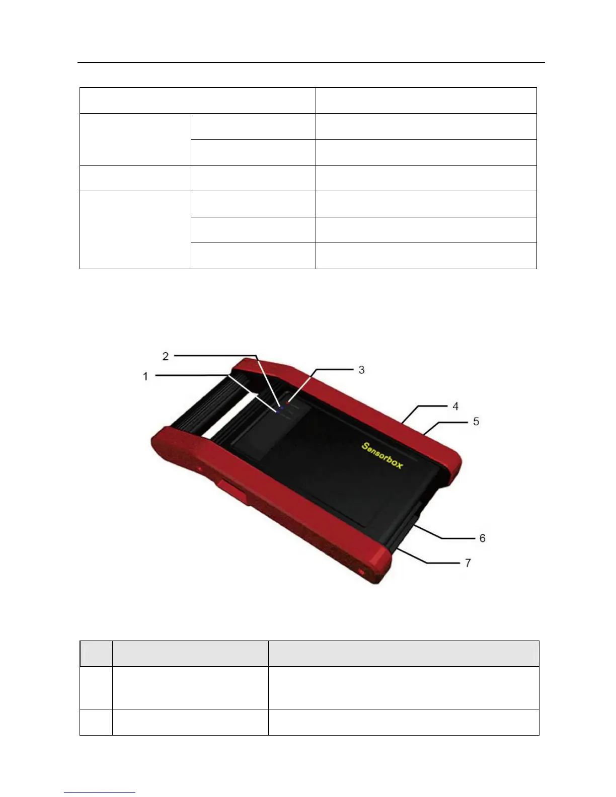
9.2.1 Sensorbox structure
Fig. 9-1 Structural diagram of Sensorbox
Table 9-1 shows the ports and indicators for X-431 Throttle sensorbox
No. Name Description
1 Data receiving indicator
Indicator (green) for receiving data from main
unit.
2 Data sending indicator Indicator (green) for sending data to main