X-431 Throttle User Manual
88
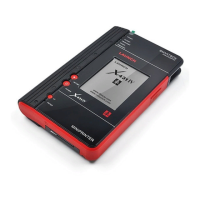
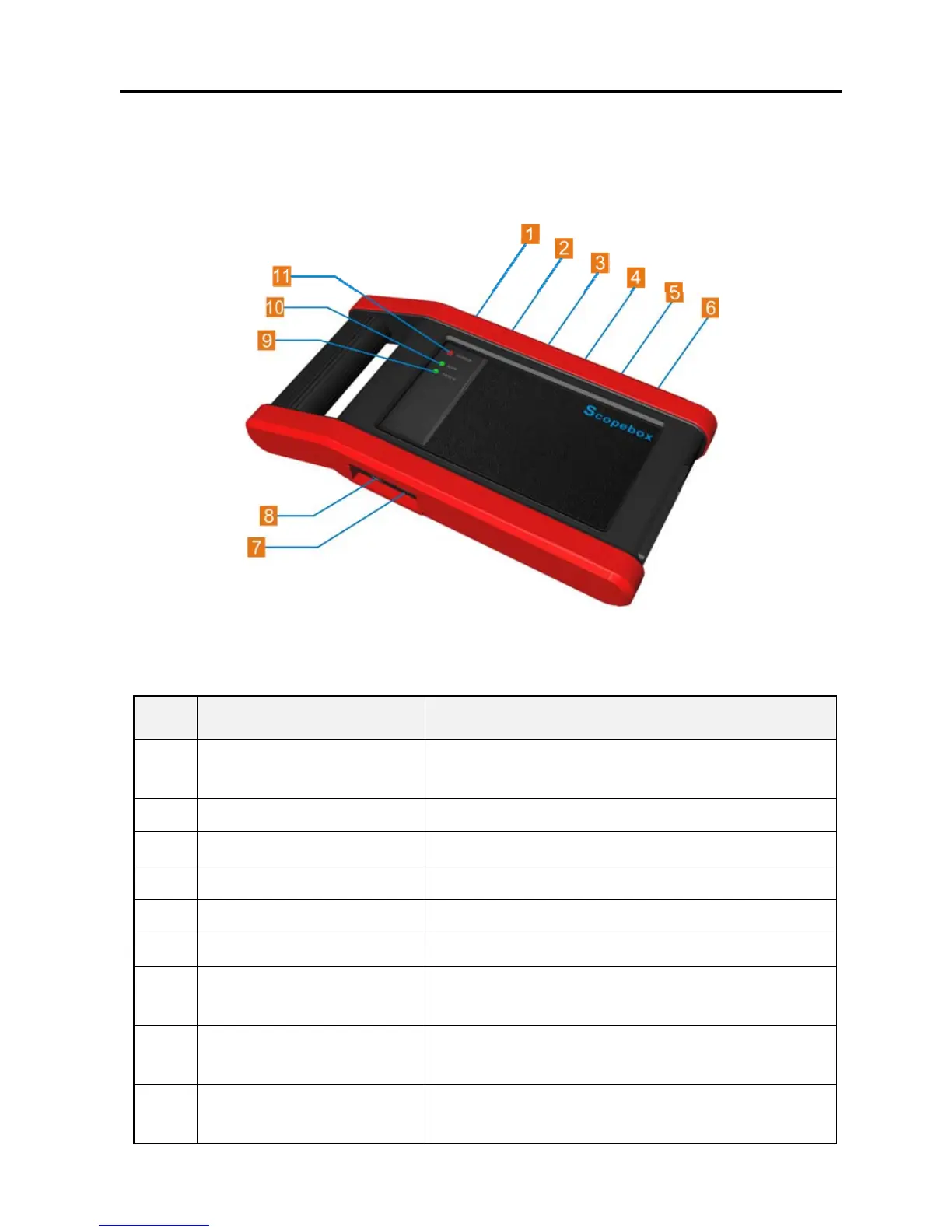
12.2 Structure & Accessories
12.2.1 Scopebox structure
Fig 12-1 Scopebox Structure Diagram
Table 12-1 shows the ports and indicators for the Scopebox.
No. Name Description
1 Fixed signal generator
Generate a square signal with fixed 1K
frequency.
2 CH1 Channel 1
3 CH2 Channel 2
4 CH3 Channel 3
5 CH4 Channel 4
6 External trigger External trigger signal
7
B-shaped USB
interface
Connect main unit via USB cable as
separated individual USB devices.
8 Power interface
Connect to power supply via the power
adapter.
9
Communication
indicator
It blinks in process of data communication.