LAUNCH X-431 Throttle User Manual
71
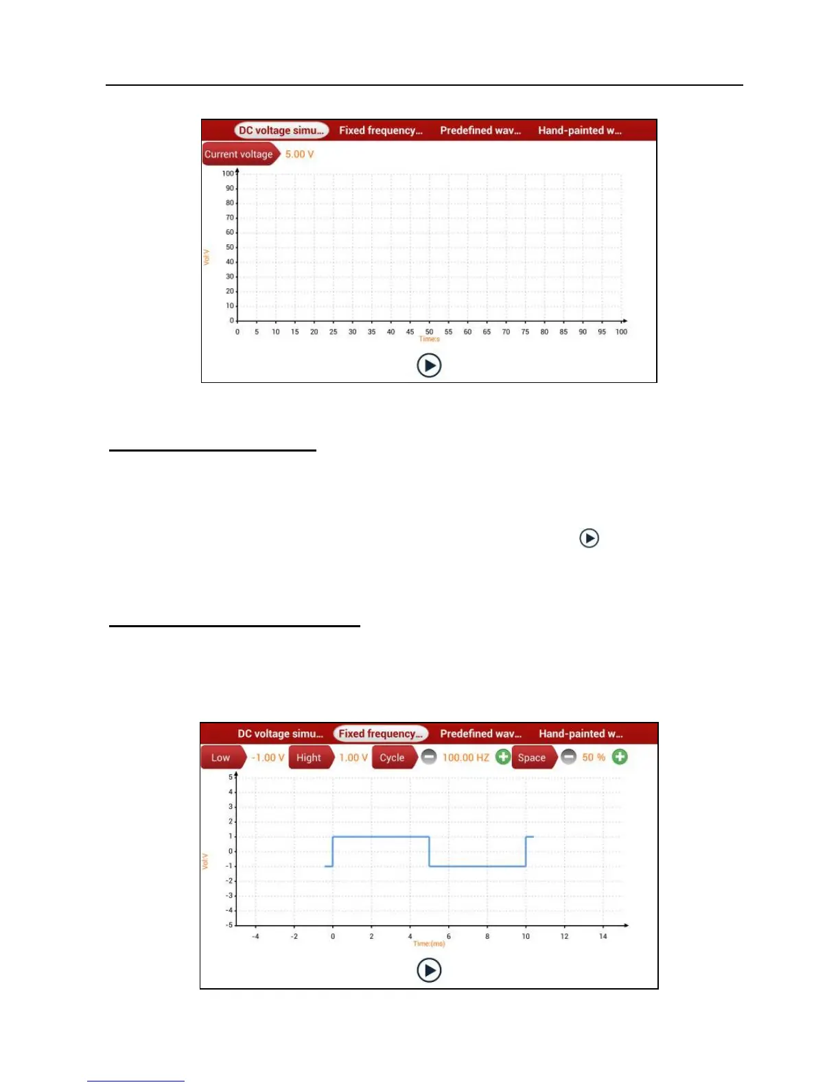
Fig. 9-2
1. DC voltage simulation
In Fig. 9-2, tap [Current voltage], then tap “+” or “-” to adjust the output voltage
value. Alternatively, user can also tap edit box, then use the on-screen keyboard
to input the desired value directly. After selecting or inputting the desired voltage
based on the working characteristics of sensor, tap the
button, then the
X-431 Throttle will begin to output the simulation voltages. Please note the red
probe is the output terminal of simulation voltage.
2. Fixed frequency simulation
This option enables you to simulate the square wave signal of pulse frequency
of 0.1 ~ 15 kHz, amplitude range of -5V ~ +5V and duty cycle 10% ~ 90%.
In Fig. 9-2, tap “Fixed frequency simulation” to enter a screen similar to Fig. 9-3.
Fig. 9-3