PowerTrace Serial User´s Guide 1 0
©1989-2018 Lauterbach GmbH
X113 DO NOT SET!
Pin 1: Connected to pin 25 of the target connector
Pin 2: GND
Pin27 Set: Connects pin 27 of the target connector to pin 14 (WD) of AUTO26
Open: pin 14 of Auto26 is open
Pin31 Set: Connects pin 31 of the target connector to pin 22 (BREQ) of AUTO26
Open: pin 22 of Auto26 is open
Pin33 Set: Connects pin 27 of the target connector to pin 24 (BGNT) of AUTO26
Open: pin 24 of Auto26 is open
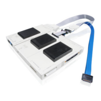
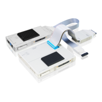
Both debug connectors AUTO26 [A] or the JTAG14 [B] hold the same debug
signals coming from the target connector [C]. Only one debug connector must
be used at the time.
Jumper Function