PowerTrace Serial User´s Guide 2 1
©1989-2018 Lauterbach GmbH
Software Installation
TRACE32 PowerView includes debug and trace tool support. An extra software installation is not required.
Additional license keys might be required, if architectures other than architecture covered by the included
module license wants to be used.
Recommendation for the Software Start
1. Power off Target and TRACE32 hardware.
2. Disconnect the debug cable and trace cable from the target.
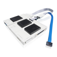
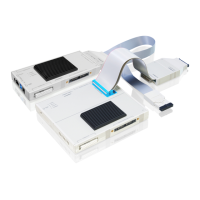
3. Ensure that any required adapters (e.g. LA-3556) and cables are connected to the
PowerTrace Serial.
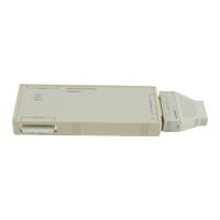
From functional point of view the adapter LA-3525 belongs to the target side and should not be
connected to the PowerTrace Serial.
4. Start the TRACE32 software.
5. Connect the debug and trace cables to the target.
- If there is no appropriate jack on your target, you can also connect the debug cable to the
debug port of Serial Port 0 if this port is planned to be used (for ARM/Mipi conform devices
only).
- Alternatively, connect the debug cable to an additional converter PCB, which splits debug and
trace signals. The converter PCB needs to be ordered separately at Lauterbach.
6. Connect the Serial Port 0 to your target’s trace port by using the flex extension cable delivered
with your accessory set. For some architectures, port sizes greater than 6 lanes or other trace
protocols like PCIe, you need to use Serial Port 1.
7. Switch the target power on.
8. Run your start-up script.
Recommendation for Power Down
1. Switch off the target power.
2. Disconnect the debug cable and trace flex extension cable from the target.
3. Shut down the TRACE32 PowerView GUI.
4. Switch off the TRACE32 hardware.
NOTE: Cable/adapter sets called “accessory set” have to be ordered additionally.