PowerTrace Serial User´s Guide 3 7
©1989-2018 Lauterbach GmbH
Diagnosis Check List
In this section:
• Basic Checks
• Advanced Checks
Basic Checks
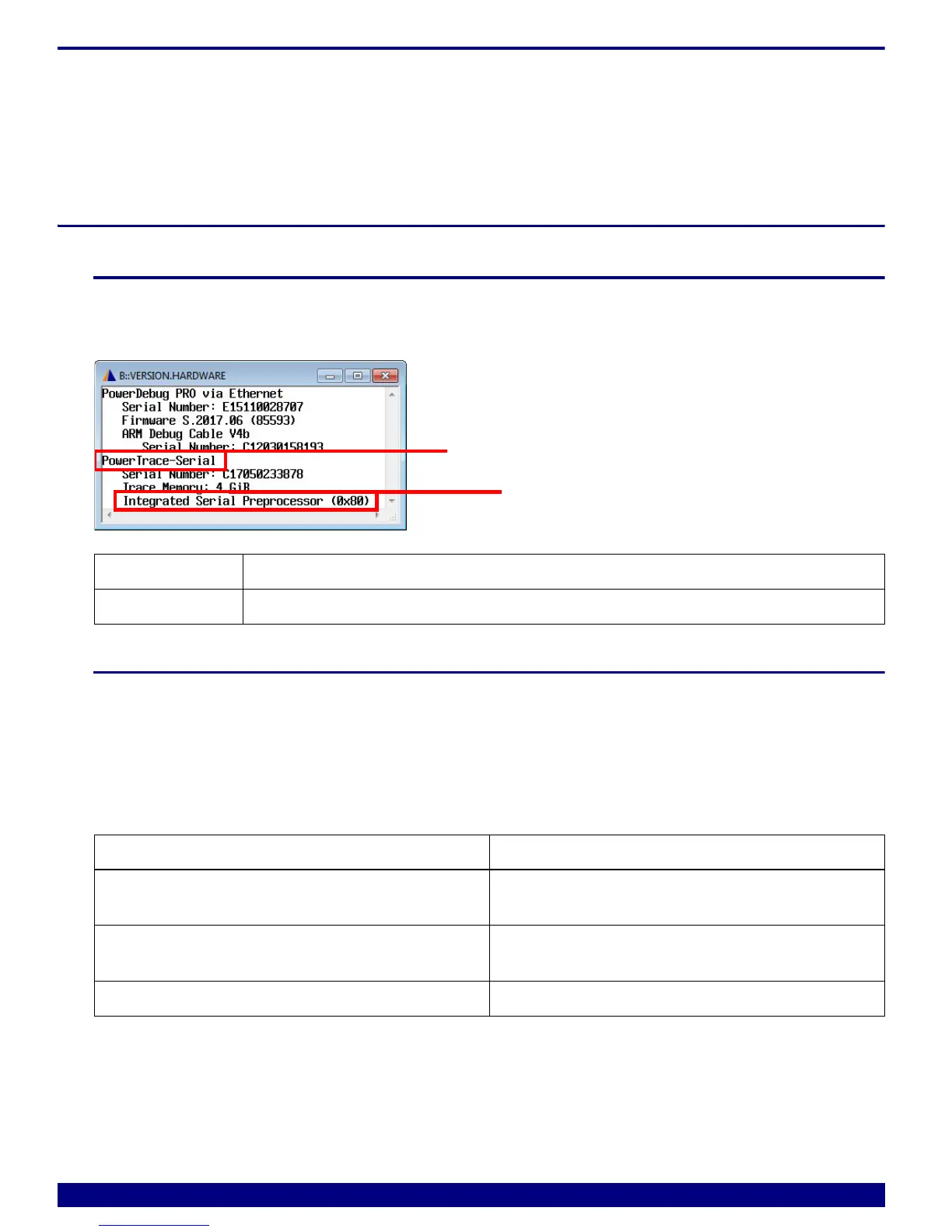
1. Check
Check the preprocessor seen by the TRACE32 software. VERSION.HARDWARE shows all detected
hardware.
2. Check
Check the trace port pinout. Lauterbach tools assume that the trace port pinout follows exactly the trace
specification of the used architecture (please refer to Connector Layout).
Did the PowerTrace Serial work for other targets? If yes, what has changed on your new target board? Often
messages such as Trace test failed: not enough samples in the trace or Trace test failed: pin
connection error might indicate the source of the error.
Also check the voltage level of the reference voltage. It is used as a reference for trigger and Vendor-I/O
signals. It should correspond to the amplitude of your trigger signal.
ID Preprocessor
0x80 Integrated Serial
Error message Possible reason
Trace test failed:
not enough samples in the trace
• Trace port does not send data
Trace test failed:
pin connection error
• Trace port data format differs from the
expected
Serial trace connection had errors
• The serial link is not stable