PowerTrace Serial User´s Guide 5
©1989-2018 Lauterbach GmbH
Installation
In this section:
• Hardware Installation
• Software Installation
Hardware Installation
PowerTrace Serial
1. Connect the PODBUS EXPRESS IN connector to the PODBUS EXPRESS OUT connector of
the PowerDebug II / PowerDebug Pro interface. Please ensure correct positioning. The
connectors must be clean and without any damage.
2. Connect the flex cable and, if necessary, the debug cable to Serial Port 0 or Serial Port 1 of the
PowerTrace Serial.
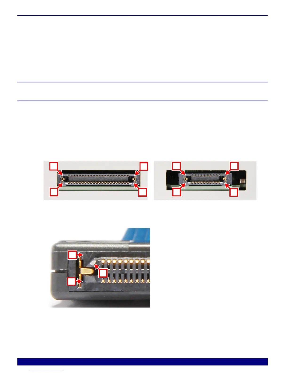
Check the connector orientation of tool and target, there are two 45° corners [A] and two 90° corners
[B]:
The marker of pin 1 [C] of the plug is easy to miss, but is located close to one 45° corner [A]. For
better illustration the picture below is rotated of 180°:
A 45° conners B 90° conners
C Pin 1 marker