PowerTrace Serial User´s Guide 4 8
©1989-2018 Lauterbach GmbH
Simulation Model
Simulation Data Request
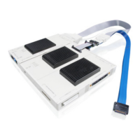
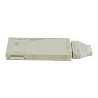
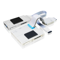
PowerTrace Serial
Models of the FPGA and the connector are required to simulate the input stage of PowerTrace Serial. Please
contact Xilinx and Samtec for device simulation models:
Xilinx FPGA: Kintex7 XC7K320T-3, FF900, GTX-transceiver
Samtec connector: ERF8 series, 80pin, right-angle
Dimensions
tbd.
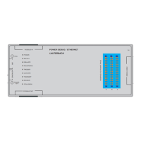
Connector Layout
SerialPort 0
The Serial Port 0 is designed for HSSTP trace ports. The use of the flex extension cable (LA-1235) let the
Serial Port 0 follow the ARM-HSSTP standard. The debug signals will be routed to the 34pin debug
connector on the top of the PowerTrace Serial module and can be accessed for debug cable.
The Serial Port 0 will also be used for non-HSSTP targets. In this case additional adapters could be
necessary.
SerialPort 1
The Serial Port 1 is designed to support multiple interfaces. The function of the signals change depending
on the targets trace port. The pin-out of this connector should be seen as Lauterbach proprietary. If you want
to connect non-supported data sources please contact the Lauterbach support.
Connector www.samtec.com
Flex cable icrstp-support@lauterbach.com
Receiver
XC7K325T-FFG900, GTX
www.xilinx.com
PCB icrstp-support@lauterbach.com