D–4
Appendix D
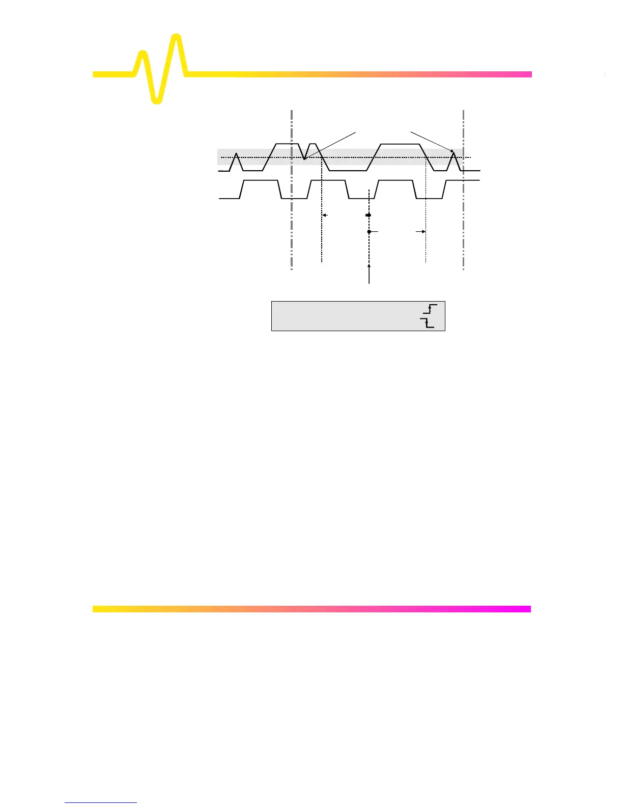
Figure D–3
Moreover, a hysteresis range may be specified to ignore any
spurious transition that does not exceed the boundaries of the
hysteresis interval. In Figure 3, ∆c2d− (1, 2) measures the time
interval separating the rising edge of the clock (trigger) from the
first negative transition of the data signal. Similarly, ∆c2d+ (1, 2)
measures the time interval between the trigger and the next
transition of the data signal.
LEFT CURSOR
TRIGGER POINT
DATA (1)
CLK (2)
CLOCK EDGE = Positive Transition
DATA EDGE = Negative Transition
HYSTERESIS
Noisy spikes ignored due
to Hysteresis band
∆−
c2d(1, 2)

 Loading...


