4–9
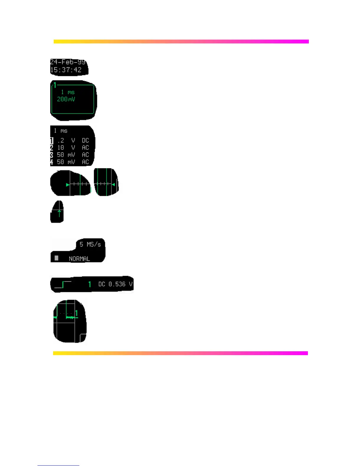
Real-Time Clock field: powered by a battery-backed real-time
clock, it displays the current date and time.
Displayed Trace Label indicates each channel or channel
displayed, the time/div and volts/div settings, and cursor
readings where appropriate. It indicates the acquisition
parameters set when the trace was captured or processed, while
the Acquisition Summary field (below) indicates the present
setting.
Acquisition Summary field: timebase, volts/div, probe
attenuation and coupling for each channel, with the selected
channel highlighted. It indicates the present setting, while the
acquisition parameters set when the trace was captured or
processed are indicated in the Displayed Trace label (above).
Trigger Level arrows on both sides of the grid that mark the
trigger voltage level relative to ground level.
Trigger Delay: an arrow indicating the trigger time relative to
the trace. The delay can be adjusted from zero to ten grid
divisions (pre-trigger), or zero to −10 000 (post-trigger) off-
screen. Pre-trigger delay appears as the upward-pointing arrow,
while post-trigger is given as a delay in seconds.
Trigger Status field shows sample rate and trigger re-arming
status (AUTO, NORMAL, SINGLE, STOPPED). The small
square icon flashes to indicate that an acquisition has been
made.
Trigger Configuration field: icon indicating type of trigger, and
information on the trigger’s source, slope, level and coupling,
and other information when appropriate.
Trace and Ground Level: trace number and ground-level
marker.

 Loading...


