5–5
ProBus System LeCroy’s ProBus system provides a complete measurement
solution from probe tip to oscilloscope display. This intelligent
interconnection between LeCroy oscilloscopes and a growing range
of accessories is achieved via a six-wire bus following Philips’ I
2
C
protocol. It provides major benefits over standard BNC or even
probe-ring connections:
Ø Autosensing the probe type, eliminating all the guesswork —
and the errors — from manually setting attenuation or
amplification factors, and ensuring proper input coupling.
Ø Transparent gain and offset control right from the front panel
— particularly useful for FET (FET menus shown here) and
current probes.
Ø Gain and offset correction factors are uploaded from the
ProBus EPROMS on FET probes and automatically
compensated to achieve fully calibrated measurements.
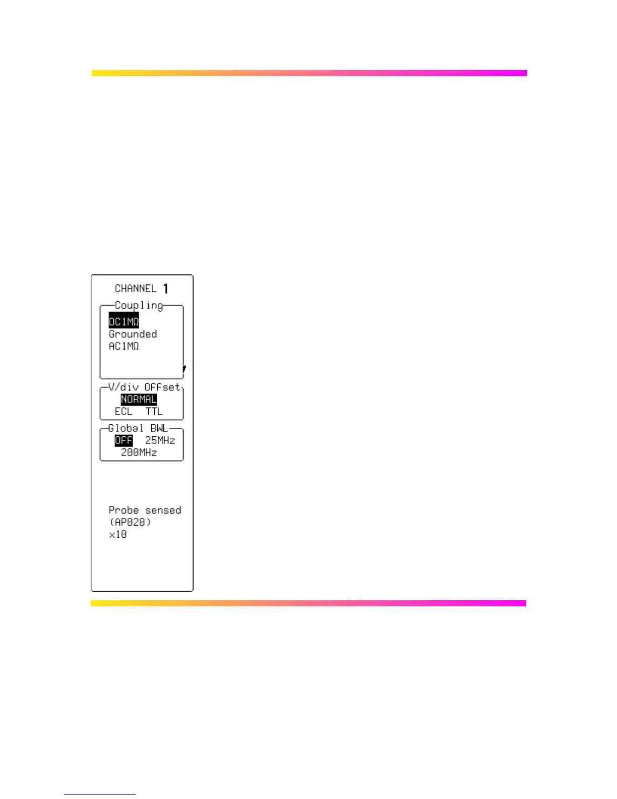
Coupling
Used to select the input channel’s coupling. If an overload is
detected, the instrument will automatically set the channel to the
grounded state: the menu can then be reset to the desired coupling.
V/div Offset
When NORMAL is highlighted, pressing the corresponding menu
button sets the offset, Volts/div, and input coupling to display ECL
signals. Press the button a second time and the settings for TTL
signals are given. And a third time returns the settings to those used
at the last manual setup of the channel.
Global BWL
To turn the bandwidth limit “OFF” or “ON”. The bandwidth can be
reduced from 500 MHz or 1 GHz, to either 200 MHz or 25 MHz, or
30 MHz (–3dB), depending on the model (see Appendix A).
Bandwidth limiting can be useful in reducing signal and system
noise or preventing high-frequency aliasing, reducing — for
example — any high-frequency signals that may cause aliasing in
single-shot applications.
When a FET probe is used, “Probe sensed…”, automatically
appears to indicate settings. When other ProBus probes are
used, this is redefined.

 Loading...


