106 TPS1200+/TS30/TM30 Reference Line
8.3.4 Defining the Slope related to a Reference Line/Arc
)
This chapter does not apply for staking to polylines.
Description • It is possible to measure points and stake points on slopes related to a reference
line/arc. A slope can be defined and cut/fill values can then be displayed to the
slope when measuring along the reference line/arc. The slope is a plane from
the reference line/arc and extends along the length of the reference line/arc.
• Slopes can be used when measuring to a reference line/arc, staking a point rela-
tive to a reference line/arc or performing a grid stakeout relative to a reference
line/arc.
Access
step-by-step
Step 1)
activating the
slope method
Step 2)
defining the
slope parameters
Step Description
1. PROG. The PROG key opens the TPS1200+/TS30/TM30 Programs
menu.
2. Select Reference Line and press CONT (F1).
3. CONT (F1) to access REFLINE Reference Task Menu.
4. REFLINE Reference Task Menu
This screen defines the task to be performed.
Select a task except Stake to Polyline.
5. Press CONT (F1) to access REFLINE Choose Reference Line.
Select Reference page.
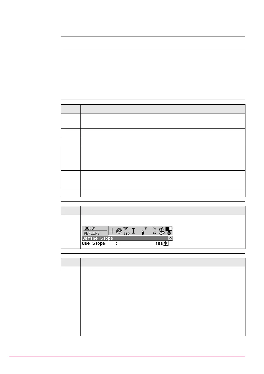
6. Press SLOPE (F3) to access REFLINE Define Slope.
Step Description
1. Ensure that <Use Slope: Yes> is selected.
Step Description
1. Defining the slope type.
Defining a slope type of <Slope Type: Left Down> creates a downward
plane extending to the left of the defined reference line/arc.
Defining a slope type of <Slope Type: Right Down> creates a downward
plane extending to the right of the defined reference line/arc.
Defining a slope type of <Slope Type: Left Up> creates an upward plane
extending to the left of the defined reference line/arc.
Defining a slope type of <Slope Type: Right Up> creates an upward
plane extending to the right of the defined reference line/arc.

 Loading...